
Features:
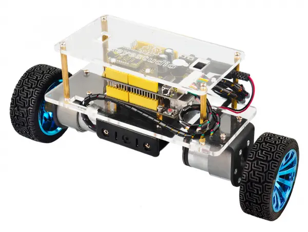
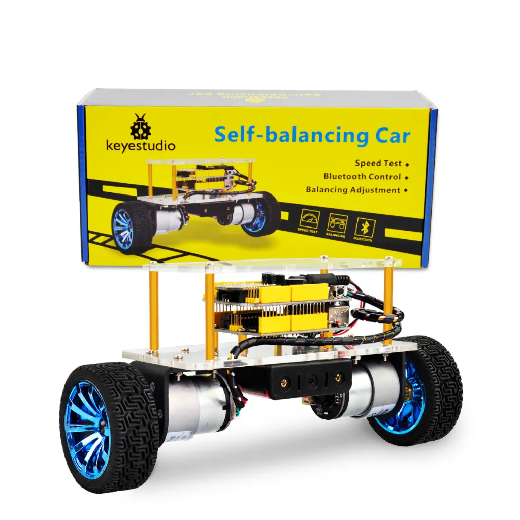
- Arduino compatible self-balancing robot kit
- Built-in MPU-6050 accelerometer and gyroscope sensor
- Motor driver based on TB6612FNG chip
- Bluetooth control using HC-06 module
- Supports Android Bluetooth control applications
- Adjustable balance angle and PID control parameters
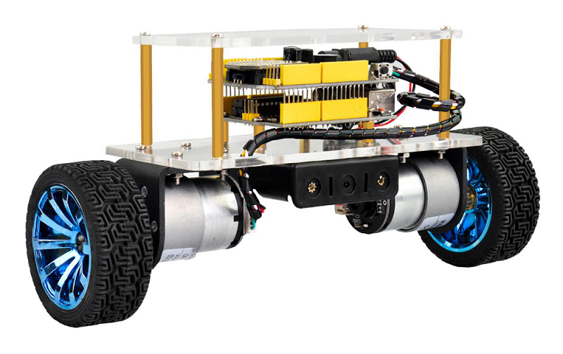
- Two DC geared motors with Hall encoders for speed feedback
- Acrylic chassis structure for lightweight design
- Educational robotics and control system learning platform
- Suitable for DIY robotics, STEM education, and PID learning
Principle of Work:
The self-balancing robot works based on dynamic balance control. The MPU-6050 sensor continuously measures the robot’s tilt angle and angular velocity. These measurements are processed by the microcontroller using filtering algorithms such as the Kalman filter to determine the robot’s current orientation.
The controller then adjusts the speed and direction of the two DC motors using PID control. When the robot tilts forward or backward, the motors move accordingly to maintain balance. Steering is achieved by changing the speed difference between the left and right motors.
The system performs three main control tasks:
- Balance Control: Maintains the robot upright by adjusting motor movement according to tilt angle.
- Speed Control: Controls forward and backward movement by adjusting the robot’s inclination.
- Direction Control: Changes direction by modifying the speed difference between the two motors.
Pinout of the Module:
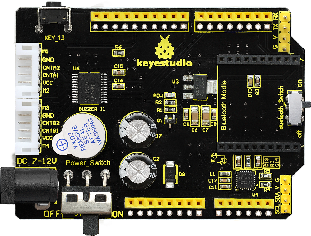
- MPU-6050 Sensor: Detects acceleration and gyroscope data for angle calculation.
- TB6612FNG Motor Driver: Controls the speed and direction of the two DC motors.
- Bluetooth Interface: Connects the HC-06 Bluetooth module for wireless control.
- Motor Connectors: Provide power and signal connections for the two DC motors.
- Power Switch: Turns the robot on or off.
- Bluetooth Switch: Enables or disables Bluetooth communication during code upload.
Applications:
- STEM robotics education
- Learning PID control algorithms
- Dynamic balance and motion control experiments
- Arduino robotics development
- Bluetooth robot control projects
- DIY robotics learning platform
Circuit:
The system integrates the controller board, balance shield, motors, and sensors into a compact robot chassis. The MPU-6050 sensor communicates with the microcontroller through the I2C interface, while the TB6612FNG motor driver controls the two DC motors through PWM signals.
Bluetooth communication is established through the serial interface using the HC-06 module.
Connecting with Arduino First Time
- Assemble the robot chassis according to the assembly guide.
- Connect the motors to the balance shield.
- Plug the HC-06 Bluetooth module into the Bluetooth interface.
- Connect the REV4 board to a computer using a USB cable.
- Open Arduino IDE and upload the balancing program.
- Disconnect the USB cable and power the robot using the battery pack.
Code:
The full project in the link in resources the bottom. We first connect the Bluetooth and then adjust the balancing angle of the car on the Bluetooth APP.
Now, we first adjust the balancing angle of the car by hand; then connect the Android Bluetooth to control the car moving via the Bluetooth APP.
Notice:
- 1)The balance shield comes with a slide switch for Bluetooth communication. When uploading the code for testing, must turn the switch OFF; or else, uploading fails.
When connected to the Bluetooth module, turn the switch ON.
- 2)Using the source code of this project, can only adjust once each time starting up; must adjust the angle first, or else the car can’t keep balance.
Source Code:
Note: Before testing the source code, do remember to add the corresponding library.
You can refer to the method in the link: https://wiki.keyestudio.com/How_to_Install_Arduino_Library
#include "MsTimer2.h"        //Internal timer2
#include "PinChangeInt.h"    //This library file can make all pins on the REV4 board as external interrupts.  Define three-axis acceleration, three-axis gyroscope variables
#include "MPU6050.h"      //MPU6050 Library
#include "Wire.h"        //IIC communication library

MPU6050 mpu6050;     // Instantiate an MPU6050 object; name mpu6050
int16_t ax, ay, az, gx, gy, gz;     //Define three-axis acceleration, three-axis gyroscope variables

//TB6612 pins definition
const int right_R1=8;
const int right_R2=12;
const int PWM_R=10;
const int left_L1=7;
const int left_L2=6;
const int PWM_L=9;

const int buz = 11;
const int btn = 13;

///////////////////////angle parameters//////////////////////////////
float angle_X; // calculate the inclined angle variable of X-axis by accelerometer
float angle_Y; //calculate the inclined angle variable of Y-axis by accelerometer
float angle0 = 0; //mechanical balance angle (ideally 0 degrees)
float Gyro_x,Gyro_y,Gyro_z;  //Angular angular velocity by gyroscope calculation
///////////////////////angle parameter//////////////////////////////

///////////////////////Kalman_Filter////////////////////////////
float Q_angle = 0.001;  //Covariance of gyroscope noise
float Q_gyro = 0.003;    // Covariance of gyroscope drift noise
float R_angle = 0.5;    //Covariance of accelerometer
char C_0 = 1;
float dt = 0.005; //The value of dt is the filter sampling time
float K1 = 0.05; // a function containing the Kalman gain is used to calculate the deviation of the optimal estimate
float K_0,K_1,t_0,t_1;
float angle_err;
float q_bias;    //gyroscope drift

float accelz = 0;
float angle;
float angleY_one;
float angle_speed;

float Pdot[4] = { 0, 0, 0, 0};
float P[2][2] = {{ 1, 0 }, { 0, 1 }};
float  PCt_0, PCt_1, E;
//////////////////////Kalman_Filter/////////////////////////

//////////////////////PID parameter///////////////////////////////
double kp = 34, ki = 0, kd = 0.62;                   //angle loop parameter
double kp_speed = 3.56, ki_speed = 0.072, kd_speed = 0;   // speed loop parameter
double kp_turn = 24, ki_turn = 0, kd_turn = 0.08;                 // steering loop parameter
double setp0 = 0; //angle balance point
int PD_pwm;  //angle output
float pwm1=0,pwm2=0;

//////////////////interrupt speed count/////////////////////////////
#define PinA_left 5  //external interrupt
#define PinA_right 4   //external interrupt
volatile long count_right = 0;//Used to calculate the pulse value calculated by the Hall encoder (the volatile long type is to ensure the value is valid)
volatile long count_left = 0;
int speedcc = 0;
//////////////////////pulse count/////////////////////////
int lz = 0;
int rz = 0;
int rpluse = 0;
int lpluse = 0;
int pulseright,pulseleft;
////////////////////////////////PI variable parameter//////////////////////////
float speeds_filterold=0;
float positions=0;
int flag1;
double PI_pwm;
int cc;
int speedout;
float speeds_filter;

//////////////////////////////turning PD///////////////////
int turnmax,turnmin,turnout;
float Turn_pwm = 0;
int zz=0;
int turncc=0;

//Bluetooth//
int front = 0;//forward variable
int back = 0;//backward
int left = 0;//turn left
int right = 0;//turn right
char val;

int i,button;

void setup()
{
  //set the motor control pins to OUTPUT
  pinMode(right_R1,OUTPUT);
  pinMode(right_R2,OUTPUT);
  pinMode(left_L1,OUTPUT);
  pinMode(left_L2,OUTPUT);
  pinMode(PWM_R,OUTPUT);
  pinMode(PWM_L,OUTPUT);

  //assign the initial state value
  digitalWrite(right_R1,1);
  digitalWrite(right_R2,0);
  digitalWrite(left_L1,0);
  digitalWrite(left_L2,1);
  analogWrite(PWM_R,0);
  analogWrite(PWM_L,0);

  pinMode(PinA_left, INPUT);  //speed encoder input
  pinMode(PinA_right, INPUT);

  pinMode(btn,INPUT);
  pinMode(buz,OUTPUT);

  // join I2C bus
  Wire.begin();                            //join I2C bus sequence
  Serial.begin(9600);                       //open the serial monitor and set the baud rate to 9600
  delay(1500);
  mpu6050.initialize();                       //initialize MPU6050
  delay(2);

  //5ms; use timer2 to set the timer interrupt (note: using timer2 may affects the PWM output of pin3 pin11)
  MsTimer2::set(5, DSzhongduan);    //5ms; execute the function DSzhongduan once
  MsTimer2::start();    //start interrupt
}

 //buzzer
void buzzer()
{
    for(int i=0;i<50;i++)
    {
    digitalWrite(buz,HIGH);
    delay(1);
    digitalWrite(buz,LOW);
    delay(1);
    }
    delay(50);
    for(int i=0;i<50;i++)
    {
    digitalWrite(buz,HIGH);
    delay(1);
    digitalWrite(buz,LOW);
    delay(1);
    }
}

void loop()
{
  //Serial.println(angle0);
  //Serial.print("angle= ");
  //Serial.println(angle);
  //delay(1);
  //Serial.println(PD_pwm);
  //Serial.println(pwm1);
  //Serial.println(pwm2);
  //Serial.print("pulseright = ");
  //Serial.println(pulseright);
  //Serial.print("pulseleft = ");
  //Serial.println(pulseleft);
  //Serial.println(PI_pwm);
  //Serial.println(speeds_filter);
  //Serial.println (positions);
  //Serial.println(Turn_pwm);
  //Serial.println(Gyro_z);
  //Serial.println(Turn_pwm);

  while(i<1)
  {
    button = digitalRead(btn);
    if(button == 0)
    {
      angle0=-angle;
      //Serial.println(angle0);
      buzzer();
      i++;
    }
  }
  if(Serial.available())
  {
    val = Serial.read();      //assign the value read from the serial port to val
    //Serial.println(val);
    switch(val)             //switch statement
    {
      case 'F': front=250; break;       //if val equals F,front=250,car will move forward
      case 'B': back=-250; break;       //go back
      case 'L': left=1; break;    //turn left
      case 'R': right=1; break;                         //turn right
      case 'S': front=0,back=0,left=0,right=0;break;    //stop
      case 'D': Serial.print(angle);break;
    }
  }

  //external interrupt; used to calculate the wheel speed
  attachPinChangeInterrupt(PinA_left, Code_left, CHANGE);          //PinA_left Level change triggers the external interrupt; execute the subfunction Code_left
  attachPinChangeInterrupt(PinA_right, Code_right, CHANGE);       //PinA_right Level change triggers the external interrupt; execute the subfunction Code_right
}

/////////////////////Hall count/////////////////////////
//left speed encoder count
void Code_left()
{
  count_left ++;
}
//right speed encoder count
void Code_right()
{
  count_right ++;
}
////////////////////pulse count///////////////////////
void countpluse()
{
  lz = count_left;     //assign the value counted by encoder to lz
  rz = count_right;

  count_left = 0;     //Clear count quantity
  count_right = 0;

  lpluse = lz;
  rpluse = rz;

  if ((pwm1 < 0) && (pwm2 < 0))                     //judge the car’s moving direction; if backward (PWM namely motor voltage is negative), pulse is a negative number.
  {
    rpluse = -rpluse;
    lpluse = -lpluse;
  }
  else if ((pwm1 > 0) && (pwm2 > 0))                 //if backward (PWM namely motor voltage is positive), pulse is a positive number.
  {
    rpluse = rpluse;
    lpluse = lpluse;
  }
  else if ((pwm1 < 0) && (pwm2 > 0))                 //judge the car’s moving direction; if turn left, right pulse is a positive number; left pulse is a negative number.
  {
    rpluse = rpluse;
    lpluse = -lpluse;
  }
  else if ((pwm1 > 0) && (pwm2 < 0))               //judge the car’s moving direction; if turn right, right pulse is a negative number; left pulse is a positive number.
  {
    rpluse = -rpluse;
    lpluse = lpluse;
  }

  // enter interrupt per 5ms,pulse number plus
  pulseright += rpluse;
  pulseleft += lpluse;
}

/////////////////////////////////interrupt ////////////////////////////
void DSzhongduan()
{
  sei();  //allow overall interrupt
  countpluse();        //pulse plus subfunction
  mpu6050.getMotion6(&ax, &ay, &az, &gx, &gy, &gz);     //IIC to get MPU6050 six-axis data  ax ay az gx gy gz
  angle_calculate(ax, ay, az, gx, gy, gz, dt, Q_angle, Q_gyro, R_angle, C_0, K1);      //get angle and Kalmam filtering
  PD();         //angle loop PD control
  anglePWM();

  cc++;
  if(cc>=8)     //5*8=40,enter PI algorithm of speed per 40ms
  {
    speedpiout();
    cc=0;  //Clear
  }
  turncc++;
  if(turncc>4)       //20ms; enter PD algorithm of steering
  {
    turnspin();
    turncc=0;     //Clear
  }
}
///////////////////////////////////////////////////////////

/////////////////////////////tilt calculation///////////////////////
void angle_calculate(int16_t ax,int16_t ay,int16_t az,int16_t gx,int16_t gy,int16_t gz,float dt,float Q_angle,float Q_gyro,float R_angle,float C_0,float K1)
{
  float Angle = -atan2(ay , az) * (180/ PI);           //Radial rotation angle calculation formula ; negative sign is direction processing
  Gyro_x = -gx / 131;              //The X-axis angular velocity calculated by the gyroscope;  the negative sign is the direction processing
  Kalman_Filter(Angle, Gyro_x);            //Kalman Filter
  //rotating angle Z-axis parameter
  Gyro_z = -gz / 131;                      //angle speed of Z-axis
  //accelz = az / 1604;

  float angleAx = -atan2(ax, az) * (180 / PI); //calculate the inclined angle with x-axis
  Gyro_y = -gy / 131.00; //angle speed of Y-axis
  Yiorderfilter(angleAx, Gyro_y); //first-order filtering
}
////////////////////////////////////////////////////////////////

///////////////////////////////KalmanFilter/////////////////////
void Kalman_Filter(double angle_m, double gyro_m)
{
  angle += (gyro_m - q_bias) * dt;          //prior estimate
  angle_err = angle_m - angle;

  Pdot[0] = Q_angle - P[0][1] - P[1][0];    //The differential of the covariance of the prior estimate error
  Pdot[1] = - P[1][1];
  Pdot[2] = - P[1][1];
  Pdot[3] = Q_gyro;

  P[0][0] += Pdot[0] * dt;    //The integral of the covariance differential of the prior estimate error
  P[0][1] += Pdot[1] * dt;
  P[1][0] += Pdot[2] * dt;
  P[1][1] += Pdot[3] * dt;

  //Intermediate variables in matrix multiplication
  PCt_0 = C_0 * P[0][0];
  PCt_1 = C_0 * P[1][0];
  //denominator
  E = R_angle + C_0 * PCt_0;
  //gain value
  K_0 = PCt_0 / E;
  K_1 = PCt_1 / E;

  t_0 = PCt_0;  //Intermediate variables in matrix multiplication
  t_1 = C_0 * P[0][1];

  P[0][0] -= K_0 * t_0;    //Posterior estimation error covariance
  P[0][1] -= K_0 * t_1;
  P[1][0] -= K_1 * t_0;
  P[1][1] -= K_1 * t_1;

  q_bias += K_1 * angle_err;    //Posterior estimate
  angle_speed = gyro_m - q_bias;   //The differential of the output value gives the optimal angular velocity
  angle += K_0 * angle_err; ////Posterior estimation; get the optimal angle
}

/////////////////////first-order filter/////////////////
void Yiorderfilter(float angle_m, float gyro_m)
{
  angleY_one = K1 * angle_m + (1 - K1) * (angleY_one + gyro_m * dt);
}

//////////////////angle PD////////////////////
void PD()
{
  PD_pwm = kp * (angle + angle0) + kd * angle_speed; //PD angle loop control
}

//////////////////speed PI////////////////////
void speedpiout()
{
  float speeds = (pulseleft + pulseright) * 1.0;      //speed  pulse value
  pulseright = pulseleft = 0;      //clear
  speeds_filterold *= 0.7;         //first-order complementary filtering
  speeds_filter = speeds_filterold + speeds * 0.3;
  speeds_filterold = speeds_filter;
  positions += speeds_filter;
  positions += front;             //Forward control fusion
  positions += back;              //backward control fusion
  positions = constrain(positions, -3550,3550);    //Anti-integral saturation
  PI_pwm = ki_speed * (setp0 - positions) + kp_speed * (setp0 - speeds_filter);      //speed loop control PI
}
//////////////////speed PI////////////////////

///////////////////////////turning/////////////////////////////////
void turnspin()
{
  int flag = 0;      //
  float turnspeed = 0;
  float rotationratio = 0;

  if (left == 1 || right == 1)
  {
    if (flag == 0)                             //judge the speed before rotate, to increase the flexibility
    {
      turnspeed = ( pulseright + pulseleft);                      //current speed ; express in pulse
      flag=1;
    }
    if (turnspeed < 0)                                 //speed absolute value
    {
      turnspeed = -turnspeed;
    }
    if(left==1||right==1)         //if press left key or right key
    {
     turnmax=3;          //max turning value
     turnmin=-3;         //min turning value
    }
    rotationratio = 5 / turnspeed;          //speed setting value
    if (rotationratio < 0.5)
    {
      rotationratio = 0.5;
    }

    if (rotationratio > 5)
    {
      rotationratio = 5;
    }
  }
  else
  {
    rotationratio = 0.5;
    flag = 0;
    turnspeed = 0;
  }
  if (left ==1)//plus according to direction parameter
  {
    turnout += rotationratio;
  }
  else if (right == 1 )//plus according to direction parameter
  {
    turnout -= rotationratio;
  }
  else turnout = 0;
  if (turnout > turnmax)   turnout = turnmax;//max value of amplitude
  if (turnout < turnmin)   turnout = turnmin;//min value of amplitude

  Turn_pwm = -turnout * kp_turn - Gyro_z * kd_turn;//turning PD algorithm control
}
///////////////////////////turning/////////////////////////////////

////////////////////////////PWM end value/////////////////////////////
void anglePWM()
{
  pwm2=-PD_pwm - PI_pwm + Turn_pwm;           //assign the end value of PWM to motor
  pwm1=-PD_pwm - PI_pwm - Turn_pwm;

  if(pwm1>255)             //limit PWM value not greater than255
  {
    pwm1=255;
  }
  if(pwm1<-255)
  {
    pwm1=-255;
  }
  if(pwm2>255)
  {
    pwm2=255;
  }
  if(pwm2<-255)
  {
    pwm2=-255;
  }

  if(angle>45 || angle<-45)      //if tilt angle is greater than 45°,motor will stop
  {
    pwm1=pwm2=0;
  }

   if(pwm2>=0)         //determine the motor steering and speed by negative and positive of PWM
  {
    digitalWrite(left_L1,LOW);
    digitalWrite(left_L2,HIGH);
    analogWrite(PWM_L,pwm2);
  }
  else
  {
    digitalWrite(left_L1,HIGH);
    digitalWrite(left_L2,LOW);
    analogWrite(PWM_L,-pwm2);
  }

  if(pwm1>=0)
  {
    digitalWrite(right_R1,LOW);
    digitalWrite(right_R2,HIGH);
    analogWrite(PWM_R,pwm1);
  }
  else
  {
    digitalWrite(right_R1,HIGH);
    digitalWrite(right_R2,LOW);
    analogWrite(PWM_R,-pwm1);
  }
}
Technical Details:
- Working Voltage: DC 9V – 12V
- Motor Driver Chip: TB6612FNG
- Motion Sensor: MPU-6050 6-axis accelerometer and gyroscope
- Motor Type: GM37-520 DC gear motor with Hall encoder
- Wheel Diameter: 68mm
- Control Platform: Arduino compatible REV4 board
- Wireless Control: HC-06 Bluetooth module
Resources:
Comparisons:
Compared with basic two-wheel robot kits, the Keyestudio Self-Balancing Car provides advanced control capabilities and learning opportunities:
- Dynamic Balance: Uses real-time sensor data to maintain upright balance automatically.
- Advanced Control Algorithms: Demonstrates PID and Kalman filtering techniques.
- Bluetooth Control: Allows wireless control through a smartphone application.
- Educational Platform: Ideal for learning robotics, motion control, and embedded programming.
- Expandable Design: Additional sensors and modules can be integrated for advanced projects.
Features:
- Arduino compatible self-balancing robot kit
- Built-in MPU-6050 accelerometer and gyroscope sensor
- Motor driver based on TB6612FNG chip
- Bluetooth control using HC-06 module
- Supports Android Bluetooth control applications
- Adjustable balance angle and PID control parameters
- Two DC geared motors with Hall encoders for speed feedback
- Acrylic chassis structure for lightweight design
- Educational robotics and control system learning platform
- Suitable for DIY robotics, STEM education, and PID learning
Principle of Work:
The self-balancing robot works based on dynamic balance control. The MPU-6050 sensor continuously measures the robot’s tilt angle and angular velocity. These measurements are processed by the microcontroller using filtering algorithms such as the Kalman filter to determine the robot’s current orientation.
The controller then adjusts the speed and direction of the two DC motors using PID control. When the robot tilts forward or backward, the motors move accordingly to maintain balance. Steering is achieved by changing the speed difference between the left and right motors.
The system performs three main control tasks:
- Balance Control: Maintains the robot upright by adjusting motor movement according to tilt angle.
- Speed Control: Controls forward and backward movement by adjusting the robot’s inclination.
- Direction Control: Changes direction by modifying the speed difference between the two motors.
Pinout of the Module:
- MPU-6050 Sensor: Detects acceleration and gyroscope data for angle calculation.
- TB6612FNG Motor Driver: Controls the speed and direction of the two DC motors.
- Bluetooth Interface: Connects the HC-06 Bluetooth module for wireless control.
- Motor Connectors: Provide power and signal connections for the two DC motors.
- Power Switch: Turns the robot on or off.
- Bluetooth Switch: Enables or disables Bluetooth communication during code upload.
Applications:
- STEM robotics education
- Learning PID control algorithms
- Dynamic balance and motion control experiments
- Arduino robotics development
- Bluetooth robot control projects
- DIY robotics learning platform
Circuit:
The system integrates the controller board, balance shield, motors, and sensors into a compact robot chassis. The MPU-6050 sensor communicates with the microcontroller through the I2C interface, while the TB6612FNG motor driver controls the two DC motors through PWM signals.
Bluetooth communication is established through the serial interface using the HC-06 module.
Connecting with Arduino First Time
- Assemble the robot chassis according to the assembly guide.
- Connect the motors to the balance shield.
- Plug the HC-06 Bluetooth module into the Bluetooth interface.
- Connect the REV4 board to a computer using a USB cable.
- Open Arduino IDE and upload the balancing program.
- Disconnect the USB cable and power the robot using the battery pack.
Code:
The full project in the link in resources the bottom. We first connect the Bluetooth and then adjust the balancing angle of the car on the Bluetooth APP.
Now, we first adjust the balancing angle of the car by hand; then connect the Android Bluetooth to control the car moving via the Bluetooth APP.
Notice:
- 1)The balance shield comes with a slide switch for Bluetooth communication. When uploading the code for testing, must turn the switch OFF; or else, uploading fails.
When connected to the Bluetooth module, turn the switch ON.
- 2)Using the source code of this project, can only adjust once each time starting up; must adjust the angle first, or else the car can’t keep balance.
Source Code:
Note: Before testing the source code, do remember to add the corresponding library.
You can refer to the method in the link: https://wiki.keyestudio.com/How_to_Install_Arduino_Library
#include "MsTimer2.h"        //Internal timer2
#include "PinChangeInt.h"    //This library file can make all pins on the REV4 board as external interrupts.  Define three-axis acceleration, three-axis gyroscope variables
#include "MPU6050.h"      //MPU6050 Library
#include "Wire.h"        //IIC communication library

MPU6050 mpu6050;     // Instantiate an MPU6050 object; name mpu6050
int16_t ax, ay, az, gx, gy, gz;     //Define three-axis acceleration, three-axis gyroscope variables

//TB6612 pins definition
const int right_R1=8;
const int right_R2=12;
const int PWM_R=10;
const int left_L1=7;
const int left_L2=6;
const int PWM_L=9;

const int buz = 11;
const int btn = 13;

///////////////////////angle parameters//////////////////////////////
float angle_X; // calculate the inclined angle variable of X-axis by accelerometer
float angle_Y; //calculate the inclined angle variable of Y-axis by accelerometer
float angle0 = 0; //mechanical balance angle (ideally 0 degrees)
float Gyro_x,Gyro_y,Gyro_z;  //Angular angular velocity by gyroscope calculation
///////////////////////angle parameter//////////////////////////////

///////////////////////Kalman_Filter////////////////////////////
float Q_angle = 0.001;  //Covariance of gyroscope noise
float Q_gyro = 0.003;    // Covariance of gyroscope drift noise
float R_angle = 0.5;    //Covariance of accelerometer
char C_0 = 1;
float dt = 0.005; //The value of dt is the filter sampling time
float K1 = 0.05; // a function containing the Kalman gain is used to calculate the deviation of the optimal estimate
float K_0,K_1,t_0,t_1;
float angle_err;
float q_bias;    //gyroscope drift

float accelz = 0;
float angle;
float angleY_one;
float angle_speed;

float Pdot[4] = { 0, 0, 0, 0};
float P[2][2] = {{ 1, 0 }, { 0, 1 }};
float  PCt_0, PCt_1, E;
//////////////////////Kalman_Filter/////////////////////////

//////////////////////PID parameter///////////////////////////////
double kp = 34, ki = 0, kd = 0.62;                   //angle loop parameter
double kp_speed = 3.56, ki_speed = 0.072, kd_speed = 0;   // speed loop parameter
double kp_turn = 24, ki_turn = 0, kd_turn = 0.08;                 // steering loop parameter
double setp0 = 0; //angle balance point
int PD_pwm;  //angle output
float pwm1=0,pwm2=0;

//////////////////interrupt speed count/////////////////////////////
#define PinA_left 5  //external interrupt
#define PinA_right 4   //external interrupt
volatile long count_right = 0;//Used to calculate the pulse value calculated by the Hall encoder (the volatile long type is to ensure the value is valid)
volatile long count_left = 0;
int speedcc = 0;
//////////////////////pulse count/////////////////////////
int lz = 0;
int rz = 0;
int rpluse = 0;
int lpluse = 0;
int pulseright,pulseleft;
////////////////////////////////PI variable parameter//////////////////////////
float speeds_filterold=0;
float positions=0;
int flag1;
double PI_pwm;
int cc;
int speedout;
float speeds_filter;

//////////////////////////////turning PD///////////////////
int turnmax,turnmin,turnout;
float Turn_pwm = 0;
int zz=0;
int turncc=0;

//Bluetooth//
int front = 0;//forward variable
int back = 0;//backward
int left = 0;//turn left
int right = 0;//turn right
char val;

int i,button;

void setup()
{
  //set the motor control pins to OUTPUT
  pinMode(right_R1,OUTPUT);
  pinMode(right_R2,OUTPUT);
  pinMode(left_L1,OUTPUT);
  pinMode(left_L2,OUTPUT);
  pinMode(PWM_R,OUTPUT);
  pinMode(PWM_L,OUTPUT);

  //assign the initial state value
  digitalWrite(right_R1,1);
  digitalWrite(right_R2,0);
  digitalWrite(left_L1,0);
  digitalWrite(left_L2,1);
  analogWrite(PWM_R,0);
  analogWrite(PWM_L,0);

  pinMode(PinA_left, INPUT);  //speed encoder input
  pinMode(PinA_right, INPUT);

  pinMode(btn,INPUT);
  pinMode(buz,OUTPUT);

  // join I2C bus
  Wire.begin();                            //join I2C bus sequence
  Serial.begin(9600);                       //open the serial monitor and set the baud rate to 9600
  delay(1500);
  mpu6050.initialize();                       //initialize MPU6050
  delay(2);

  //5ms; use timer2 to set the timer interrupt (note: using timer2 may affects the PWM output of pin3 pin11)
  MsTimer2::set(5, DSzhongduan);    //5ms; execute the function DSzhongduan once
  MsTimer2::start();    //start interrupt
}

 //buzzer
void buzzer()
{
    for(int i=0;i<50;i++)
    {
    digitalWrite(buz,HIGH);
    delay(1);
    digitalWrite(buz,LOW);
    delay(1);
    }
    delay(50);
    for(int i=0;i<50;i++)
    {
    digitalWrite(buz,HIGH);
    delay(1);
    digitalWrite(buz,LOW);
    delay(1);
    }
}

void loop()
{
  //Serial.println(angle0);
  //Serial.print("angle= ");
  //Serial.println(angle);
  //delay(1);
  //Serial.println(PD_pwm);
  //Serial.println(pwm1);
  //Serial.println(pwm2);
  //Serial.print("pulseright = ");
  //Serial.println(pulseright);
  //Serial.print("pulseleft = ");
  //Serial.println(pulseleft);
  //Serial.println(PI_pwm);
  //Serial.println(speeds_filter);
  //Serial.println (positions);
  //Serial.println(Turn_pwm);
  //Serial.println(Gyro_z);
  //Serial.println(Turn_pwm);

  while(i<1)
  {
    button = digitalRead(btn);
    if(button == 0)
    {
      angle0=-angle;
      //Serial.println(angle0);
      buzzer();
      i++;
    }
  }
  if(Serial.available())
  {
    val = Serial.read();      //assign the value read from the serial port to val
    //Serial.println(val);
    switch(val)             //switch statement
    {
      case 'F': front=250; break;       //if val equals F,front=250,car will move forward
      case 'B': back=-250; break;       //go back
      case 'L': left=1; break;    //turn left
      case 'R': right=1; break;                         //turn right
      case 'S': front=0,back=0,left=0,right=0;break;    //stop
      case 'D': Serial.print(angle);break;
    }
  }

  //external interrupt; used to calculate the wheel speed
  attachPinChangeInterrupt(PinA_left, Code_left, CHANGE);          //PinA_left Level change triggers the external interrupt; execute the subfunction Code_left
  attachPinChangeInterrupt(PinA_right, Code_right, CHANGE);       //PinA_right Level change triggers the external interrupt; execute the subfunction Code_right
}

/////////////////////Hall count/////////////////////////
//left speed encoder count
void Code_left()
{
  count_left ++;
}
//right speed encoder count
void Code_right()
{
  count_right ++;
}
////////////////////pulse count///////////////////////
void countpluse()
{
  lz = count_left;     //assign the value counted by encoder to lz
  rz = count_right;

  count_left = 0;     //Clear count quantity
  count_right = 0;

  lpluse = lz;
  rpluse = rz;

  if ((pwm1 < 0) && (pwm2 < 0))                     //judge the car’s moving direction; if backward (PWM namely motor voltage is negative), pulse is a negative number.
  {
    rpluse = -rpluse;
    lpluse = -lpluse;
  }
  else if ((pwm1 > 0) && (pwm2 > 0))                 //if backward (PWM namely motor voltage is positive), pulse is a positive number.
  {
    rpluse = rpluse;
    lpluse = lpluse;
  }
  else if ((pwm1 < 0) && (pwm2 > 0))                 //judge the car’s moving direction; if turn left, right pulse is a positive number; left pulse is a negative number.
  {
    rpluse = rpluse;
    lpluse = -lpluse;
  }
  else if ((pwm1 > 0) && (pwm2 < 0))               //judge the car’s moving direction; if turn right, right pulse is a negative number; left pulse is a positive number.
  {
    rpluse = -rpluse;
    lpluse = lpluse;
  }

  // enter interrupt per 5ms,pulse number plus
  pulseright += rpluse;
  pulseleft += lpluse;
}

/////////////////////////////////interrupt ////////////////////////////
void DSzhongduan()
{
  sei();  //allow overall interrupt
  countpluse();        //pulse plus subfunction
  mpu6050.getMotion6(&ax, &ay, &az, &gx, &gy, &gz);     //IIC to get MPU6050 six-axis data  ax ay az gx gy gz
  angle_calculate(ax, ay, az, gx, gy, gz, dt, Q_angle, Q_gyro, R_angle, C_0, K1);      //get angle and Kalmam filtering
  PD();         //angle loop PD control
  anglePWM();

  cc++;
  if(cc>=8)     //5*8=40,enter PI algorithm of speed per 40ms
  {
    speedpiout();
    cc=0;  //Clear
  }
  turncc++;
  if(turncc>4)       //20ms; enter PD algorithm of steering
  {
    turnspin();
    turncc=0;     //Clear
  }
}
///////////////////////////////////////////////////////////

/////////////////////////////tilt calculation///////////////////////
void angle_calculate(int16_t ax,int16_t ay,int16_t az,int16_t gx,int16_t gy,int16_t gz,float dt,float Q_angle,float Q_gyro,float R_angle,float C_0,float K1)
{
  float Angle = -atan2(ay , az) * (180/ PI);           //Radial rotation angle calculation formula ; negative sign is direction processing
  Gyro_x = -gx / 131;              //The X-axis angular velocity calculated by the gyroscope;  the negative sign is the direction processing
  Kalman_Filter(Angle, Gyro_x);            //Kalman Filter
  //rotating angle Z-axis parameter
  Gyro_z = -gz / 131;                      //angle speed of Z-axis
  //accelz = az / 1604;

  float angleAx = -atan2(ax, az) * (180 / PI); //calculate the inclined angle with x-axis
  Gyro_y = -gy / 131.00; //angle speed of Y-axis
  Yiorderfilter(angleAx, Gyro_y); //first-order filtering
}
////////////////////////////////////////////////////////////////

///////////////////////////////KalmanFilter/////////////////////
void Kalman_Filter(double angle_m, double gyro_m)
{
  angle += (gyro_m - q_bias) * dt;          //prior estimate
  angle_err = angle_m - angle;

  Pdot[0] = Q_angle - P[0][1] - P[1][0];    //The differential of the covariance of the prior estimate error
  Pdot[1] = - P[1][1];
  Pdot[2] = - P[1][1];
  Pdot[3] = Q_gyro;

  P[0][0] += Pdot[0] * dt;    //The integral of the covariance differential of the prior estimate error
  P[0][1] += Pdot[1] * dt;
  P[1][0] += Pdot[2] * dt;
  P[1][1] += Pdot[3] * dt;

  //Intermediate variables in matrix multiplication
  PCt_0 = C_0 * P[0][0];
  PCt_1 = C_0 * P[1][0];
  //denominator
  E = R_angle + C_0 * PCt_0;
  //gain value
  K_0 = PCt_0 / E;
  K_1 = PCt_1 / E;

  t_0 = PCt_0;  //Intermediate variables in matrix multiplication
  t_1 = C_0 * P[0][1];

  P[0][0] -= K_0 * t_0;    //Posterior estimation error covariance
  P[0][1] -= K_0 * t_1;
  P[1][0] -= K_1 * t_0;
  P[1][1] -= K_1 * t_1;

  q_bias += K_1 * angle_err;    //Posterior estimate
  angle_speed = gyro_m - q_bias;   //The differential of the output value gives the optimal angular velocity
  angle += K_0 * angle_err; ////Posterior estimation; get the optimal angle
}

/////////////////////first-order filter/////////////////
void Yiorderfilter(float angle_m, float gyro_m)
{
  angleY_one = K1 * angle_m + (1 - K1) * (angleY_one + gyro_m * dt);
}

//////////////////angle PD////////////////////
void PD()
{
  PD_pwm = kp * (angle + angle0) + kd * angle_speed; //PD angle loop control
}

//////////////////speed PI////////////////////
void speedpiout()
{
  float speeds = (pulseleft + pulseright) * 1.0;      //speed  pulse value
  pulseright = pulseleft = 0;      //clear
  speeds_filterold *= 0.7;         //first-order complementary filtering
  speeds_filter = speeds_filterold + speeds * 0.3;
  speeds_filterold = speeds_filter;
  positions += speeds_filter;
  positions += front;             //Forward control fusion
  positions += back;              //backward control fusion
  positions = constrain(positions, -3550,3550);    //Anti-integral saturation
  PI_pwm = ki_speed * (setp0 - positions) + kp_speed * (setp0 - speeds_filter);      //speed loop control PI
}
//////////////////speed PI////////////////////

///////////////////////////turning/////////////////////////////////
void turnspin()
{
  int flag = 0;      //
  float turnspeed = 0;
  float rotationratio = 0;

  if (left == 1 || right == 1)
  {
    if (flag == 0)                             //judge the speed before rotate, to increase the flexibility
    {
      turnspeed = ( pulseright + pulseleft);                      //current speed ; express in pulse
      flag=1;
    }
    if (turnspeed < 0)                                 //speed absolute value
    {
      turnspeed = -turnspeed;
    }
    if(left==1||right==1)         //if press left key or right key
    {
     turnmax=3;          //max turning value
     turnmin=-3;         //min turning value
    }
    rotationratio = 5 / turnspeed;          //speed setting value
    if (rotationratio < 0.5)
    {
      rotationratio = 0.5;
    }

    if (rotationratio > 5)
    {
      rotationratio = 5;
    }
  }
  else
  {
    rotationratio = 0.5;
    flag = 0;
    turnspeed = 0;
  }
  if (left ==1)//plus according to direction parameter
  {
    turnout += rotationratio;
  }
  else if (right == 1 )//plus according to direction parameter
  {
    turnout -= rotationratio;
  }
  else turnout = 0;
  if (turnout > turnmax)   turnout = turnmax;//max value of amplitude
  if (turnout < turnmin)   turnout = turnmin;//min value of amplitude

  Turn_pwm = -turnout * kp_turn - Gyro_z * kd_turn;//turning PD algorithm control
}
///////////////////////////turning/////////////////////////////////

////////////////////////////PWM end value/////////////////////////////
void anglePWM()
{
  pwm2=-PD_pwm - PI_pwm + Turn_pwm;           //assign the end value of PWM to motor
  pwm1=-PD_pwm - PI_pwm - Turn_pwm;

  if(pwm1>255)             //limit PWM value not greater than255
  {
    pwm1=255;
  }
  if(pwm1<-255)
  {
    pwm1=-255;
  }
  if(pwm2>255)
  {
    pwm2=255;
  }
  if(pwm2<-255)
  {
    pwm2=-255;
  }

  if(angle>45 || angle<-45)      //if tilt angle is greater than 45°,motor will stop
  {
    pwm1=pwm2=0;
  }

   if(pwm2>=0)         //determine the motor steering and speed by negative and positive of PWM
  {
    digitalWrite(left_L1,LOW);
    digitalWrite(left_L2,HIGH);
    analogWrite(PWM_L,pwm2);
  }
  else
  {
    digitalWrite(left_L1,HIGH);
    digitalWrite(left_L2,LOW);
    analogWrite(PWM_L,-pwm2);
  }

  if(pwm1>=0)
  {
    digitalWrite(right_R1,LOW);
    digitalWrite(right_R2,HIGH);
    analogWrite(PWM_R,pwm1);
  }
  else
  {
    digitalWrite(right_R1,HIGH);
    digitalWrite(right_R2,LOW);
    analogWrite(PWM_R,-pwm1);
  }
}
Technical Details:
- Working Voltage: DC 9V – 12V
- Motor Driver Chip: TB6612FNG
- Motion Sensor: MPU-6050 6-axis accelerometer and gyroscope
- Motor Type: GM37-520 DC gear motor with Hall encoder
- Wheel Diameter: 68mm
- Control Platform: Arduino compatible REV4 board
- Wireless Control: HC-06 Bluetooth module
Resources:
Comparisons:
Compared with basic two-wheel robot kits, the Keyestudio Self-Balancing Car provides advanced control capabilities and learning opportunities:
- Dynamic Balance: Uses real-time sensor data to maintain upright balance automatically.
- Advanced Control Algorithms: Demonstrates PID and Kalman filtering techniques.
- Bluetooth Control: Allows wireless control through a smartphone application.
- Educational Platform: Ideal for learning robotics, motion control, and embedded programming.
- Expandable Design: Additional sensors and modules can be integrated for advanced projects.