

Features:
- Dual-core 64-bit RISC-V processor (up to 400MHz)
- Built-in AI acceleration for machine vision and deep learning
- Integrated ESP8285 Wi-Fi module
- Supports 2.4GHz and 5GHz Wi-Fi via external antenna design
- Low power consumption for embedded applications
- Supports MaixPy (MicroPython) and C/C++ development
- High-speed USB Type-C interface with CH340
- MicroSD card slot for storage expansion
- DVP camera interface for image processing
- LCD interface for display output
- Full GPIO access via 2×20 header
- Onboard reset and user buttons
Principle of Work:
The MAix BiT operates by executing AI algorithms directly on its onboard RISC-V processor with built-in neural network acceleration. This allows it to process data locally without sending it to external servers. Data from connected devices such as cameras or sensors is collected through onboard interfaces. The processor then applies AI models to analyze this data in real time, enabling tasks like object detection, facial recognition, or pattern analysis. The processed data can be transmitted via Wi-Fi to other systems or used locally to control outputs such as displays, motors, or alerts. This edge computing approach reduces latency, improves privacy, and increases system reliability.
Pinout of the Module:

- V3.3: 3.3V power supply
- VIN: External power input (4.5V–5.5V)
- GND: Ground
- ADC: Analog input (0–1.8V)
- GPIO0–GPIO19: General-purpose I/O pins
- SCK, MISO, MOSI, SS: SPI communication interface
- TXD, RXD: UART communication
- RST: Reset pin

Applications:
- AI-based object recognition systems
- Smart home automation devices
- Industrial automation and monitoring
- Robotics and autonomous systems
- Speech and voice recognition systems
- Environmental monitoring
- Edge AI computing platforms
- Educational AI and IoT projects
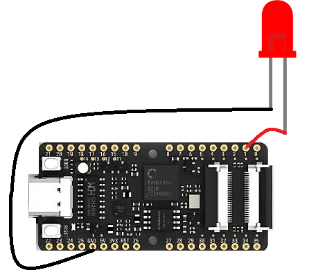
Circuit (LED Blink Example):
- Connect LED anode (long leg) to GPIO4
- Connect LED cathode (short leg) to GND
- Use a 220Ω resistor in series with the LED
- Connect the board to PC using USB Type-C
Connecting with First Time (MaixPy Setup)
- Download MaixPy firmware and IDE from Sipeed GitHub
- Install USB drivers from the provided package
- Connect the board using USB Type-C cable
- Open MaixPy IDE and select the correct serial port
- Upload firmware or scripts directly to the board
Code (LED Blink):
from machine import Pin
import time

led = Pin(4, Pin.OUT)

while True:
    led.value(1)
    time.sleep(0.5)
    led.value(0)
    time.sleep(0.5)
Technical Details:
- Processor: Dual-core 64-bit RISC-V (up to 400MHz)
- AI Engine: Built-in neural network accelerator
- Flash Memory: 8MB
- SRAM: 6MB
- Wi-Fi Module: ESP8285
- GPIO Interface: 2×20 header
- USB Interface: Type-C with CH340
- Storage: MicroSD (TF card supported)
- Camera Interface: DVP (24-pin FPC)
- Display Interface: LCD (24-pin FPC)
Resources:
- Sipeed MAix Documentation
- MaixPy IDE and Firmware
- Kendryte K210 Datasheet
- Machine Vision Libraries for MAix
Comparisons:
Compared with ESP32-based boards, the MAix BiT provides advanced AI capabilities:
- AI Acceleration: Built-in hardware for neural network processing
- Higher AI Performance: Suitable for image and vision tasks
- Edge Computing: Processes data locally without cloud dependency
- More Memory: Larger RAM and flash for AI applications
- Specialized Use: Designed for AI + IoT instead of general-purpose control
Features:
- Dual-core 64-bit RISC-V processor (up to 400MHz)
- Built-in AI acceleration for machine vision and deep learning
- Integrated ESP8285 Wi-Fi module
- Supports 2.4GHz and 5GHz Wi-Fi via external antenna design
- Low power consumption for embedded applications
- Supports MaixPy (MicroPython) and C/C++ development
- High-speed USB Type-C interface with CH340
- MicroSD card slot for storage expansion
- DVP camera interface for image processing
- LCD interface for display output
- Full GPIO access via 2×20 header
- Onboard reset and user buttons
Principle of Work:
The MAix BiT operates by executing AI algorithms directly on its onboard RISC-V processor with built-in neural network acceleration. This allows it to process data locally without sending it to external servers. Data from connected devices such as cameras or sensors is collected through onboard interfaces. The processor then applies AI models to analyze this data in real time, enabling tasks like object detection, facial recognition, or pattern analysis. The processed data can be transmitted via Wi-Fi to other systems or used locally to control outputs such as displays, motors, or alerts. This edge computing approach reduces latency, improves privacy, and increases system reliability.
Pinout of the Module:
- V3.3: 3.3V power supply
- VIN: External power input (4.5V–5.5V)
- GND: Ground
- ADC: Analog input (0–1.8V)
- GPIO0–GPIO19: General-purpose I/O pins
- SCK, MISO, MOSI, SS: SPI communication interface
- TXD, RXD: UART communication
- RST: Reset pin
Applications:
- AI-based object recognition systems
- Smart home automation devices
- Industrial automation and monitoring
- Robotics and autonomous systems
- Speech and voice recognition systems
- Environmental monitoring
- Edge AI computing platforms
- Educational AI and IoT projects
Circuit (LED Blink Example):
- Connect LED anode (long leg) to GPIO4
- Connect LED cathode (short leg) to GND
- Use a 220Ω resistor in series with the LED
- Connect the board to PC using USB Type-C
Connecting with First Time (MaixPy Setup)
- Download MaixPy firmware and IDE from Sipeed GitHub
- Install USB drivers from the provided package
- Connect the board using USB Type-C cable
- Open MaixPy IDE and select the correct serial port
- Upload firmware or scripts directly to the board
Code (LED Blink):
from machine import Pin
import time

led = Pin(4, Pin.OUT)

while True:
    led.value(1)
    time.sleep(0.5)
    led.value(0)
    time.sleep(0.5)
Technical Details:
- Processor: Dual-core 64-bit RISC-V (up to 400MHz)
- AI Engine: Built-in neural network accelerator
- Flash Memory: 8MB
- SRAM: 6MB
- Wi-Fi Module: ESP8285
- GPIO Interface: 2×20 header
- USB Interface: Type-C with CH340
- Storage: MicroSD (TF card supported)
- Camera Interface: DVP (24-pin FPC)
- Display Interface: LCD (24-pin FPC)
Resources:
- Sipeed MAix Documentation
- MaixPy IDE and Firmware
- Kendryte K210 Datasheet
- Machine Vision Libraries for MAix
Comparisons:
Compared with ESP32-based boards, the MAix BiT provides advanced AI capabilities:
- AI Acceleration: Built-in hardware for neural network processing
- Higher AI Performance: Suitable for image and vision tasks
- Edge Computing: Processes data locally without cloud dependency
- More Memory: Larger RAM and flash for AI applications
- Specialized Use: Designed for AI + IoT instead of general-purpose control