Features:
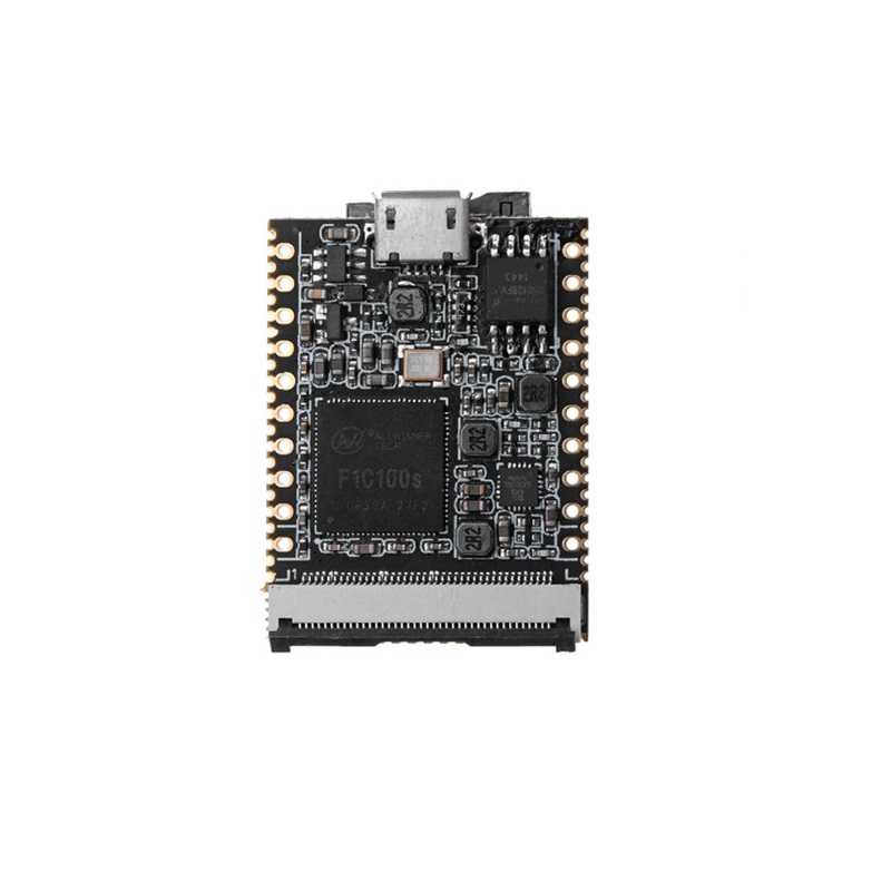
- CPU: Allwinner F1C100s, ARM926EJS core, up to 900 MHz
- Memory & Storage: 32 MB DDR integrated in SoC, 16 MB SPI Flash, onboard TF card slot for booting
- Display Support: 40-pin RGB LCD FPC connector; resolutions 272×480, 480×800, 1024×600; support for resistive and capacitive displays via adapter; 720P video output; H.264/MPEG video decoding
- Communication Interfaces: SDIO for WiFi, 2× SPI, 3× TWI/I2C, 3× UART, OTG USB, TV-out
- Other Interfaces: 2× PWM, 1× LRADC, 2× headphone outputs, 1× microphone input
- Electrical: Input 5V via micro USB or 3.3–5V via pins, output 3.3V selectable; power consumption 54 mA (idle Linux), 250 mA with display; operating temperature -20 to 70°C, storage -40 to 125°C
- Debug: UART0 serial port (Tx/Rx labeled on board)
- Boot: TF card boot or soldered SPI flash; USB-only connection does not boot the system
Specifications:
- Core Board Size: 25.4 × 33.0 mm
- Core Board Weight: 4.2 ± 0.2 g
- Power Input: 5V via micro USB or 3.3–5V via pins
- Video Output: 720P, supports H.264/MPEG decoding
- Operating Temperature: -20 to 70°C
- Storage Temperature: -40 to 125°C
- Memory: 32 MB DDR, 16 MB SPI Flash
- CPU Frequency: 24–408 MHz
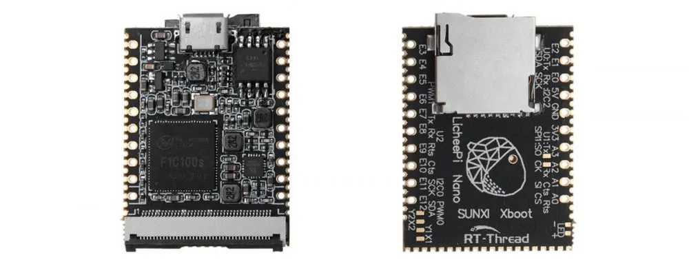
Pinout of the Module:

- UART0: System debug serial port (Tx/Rx labeled on board)
- Power Pins: 3.3–5V input pins, 3.3V output selectable
- Communication: SPI, TWI/I2C, UART, SDIO for WiFi, OTG USB
- Display: 40-pin RGB LCD connector supporting multiple resolutions
- Other I/O: PWM pins, LRADC, microphone, headphone outputs
- TF Card Slot: Boot or storage expansion
Applications:
- IoT applications with complex communication protocols
- Human-computer interaction interfaces with advanced graphical logic
- Embedded projects needing more operations than standard MCUs
- Rapid prototyping with Linux open-source software
- Educational and hobbyist projects for entry-level engineers
- High-end DIY projects balancing size, performance, and usability
Circuit:
For basic testing, you can power the board via micro-USB and connect to the UART0 serial port.
Connecting with Lichee Nano for the First Time:
- Prepare a Micro-USB cable and USB-to-TTL adapter for serial debugging
- Insert a TF card or ensure SPI flash is soldered for boot
- Connect UART0 pins (Tx/Rx) to your computer
- Power the board via Micro-USB
- Note: Only plugging in USB without a boot medium will not start the system
- Use UART0 to monitor boot messages and perform debugging
⚙️ 1. Set Up Your Windows Environment
- Install VS Code: https://code.visualstudio.com/
- Install Git: https://git‑scm.com/
- Install PuTTY (SSH & Serial): https://www.putty.org/
- Install WinSCP (file transfer): https://winscp.net/
- Install Python (optional): https://python.org/
2. Connect to the Lichee Nano
UART Debugging (Recommended)
- Connect USB‑to‑TTL adapter to UART0 pins (Tx, Rx, GND) on the board.
- Open PuTTY → Serial → Select COM port → Baud rate 115200.
- Power the board — you’ll see boot logs in PuTTY.
SSH Connection (If Board Has Network)
- Find board IP address via UART debug logs or router DHCP table.
- In PuTTY → SSH → enter board IP and port 22 → Open.
- Use Linux login (often
rootwith no password).
3. Configure VS Code for Remote Development
- Open VS Code → Extensions → install Remote – SSH
- Press
F1→ “Remote‑SSH: Connect to Host…” → add the board’s SSH address (e.g.,[email protected]) - Open a folder on the remote board to edit files directly
VS Code will now edit, build, and sync files on the Lichee Nano as if they were local.
4. Build a Simple Program on Linux
This example shows how to create a simple C app that prints text.
Create Your Source File
// hello.c #include
int main(void) {
printf("Hello from Lichee Nano!\n");
return 0;
}
Compile on the Nano
gcc -o hello hello.c ▶ Run the Program
./hello 5. Copy Files from Windows (WinSCP)
- Open WinSCP → set protocol to SCP → host = board IP → login
- Drag & drop files from Windows → remote home folder
- Use PuTTY to SSH and run the program
6. Build a Simple Bash Script
Create a script you can run from SSH:
# hello.sh echo "Hello from bash script!" chmod +x hello.sh ./hello.sh 7. Build a Qt Application (Optional)
- Install Qt Creator on Windows
- Write your UI app locally
- Cross‑compile or deploy to the Nano via SSH
8. Tips & Common Commands
- List files:
ls –l - Edit files:
nano filenameor via VS Code - Check memory/cpu:
top/free –h - Reboot:
reboot
Summary
- Your Windows PC will act as the development host
- PuTTY and UART give you low‑level access to the Nano
- VS Code + Remote SSH is the best way to edit and build software
- WinSCP lets you transfer files easily
- C, shell, Python, and Qt all work well on Linux
Code Example:
For testing the board, you can blink an LED connected to one of the GPIO pins and monitor messages over UART0:
 // Example: Blink LED on GPIO #define LED_PIN 0 // Change based on your connected GPIO
#include "stdio.h"
#include "unistd.h"
#include "f1c100s_gpio.h"
int main() {
gpio_init(LED_PIN, OUTPUT);
while(1) {
gpio_write(LED_PIN, 1);
printf("LED ON\n");
usleep(500000); // 500 ms
gpio_write(LED_PIN, 0);
printf("LED OFF\n");
usleep(500000);
}
return 0;
}
Resources:
Features:
- CPU: Allwinner F1C100s, ARM926EJS core, up to 900 MHz
- Memory & Storage: 32 MB DDR integrated in SoC, 16 MB SPI Flash, onboard TF card slot for booting
- Display Support: 40-pin RGB LCD FPC connector; resolutions 272×480, 480×800, 1024×600; support for resistive and capacitive displays via adapter; 720P video output; H.264/MPEG video decoding
- Communication Interfaces: SDIO for WiFi, 2× SPI, 3× TWI/I2C, 3× UART, OTG USB, TV-out
- Other Interfaces: 2× PWM, 1× LRADC, 2× headphone outputs, 1× microphone input
- Electrical: Input 5V via micro USB or 3.3–5V via pins, output 3.3V selectable; power consumption 54 mA (idle Linux), 250 mA with display; operating temperature -20 to 70°C, storage -40 to 125°C
- Debug: UART0 serial port (Tx/Rx labeled on board)
- Boot: TF card boot or soldered SPI flash; USB-only connection does not boot the system
Specifications:
- Core Board Size: 25.4 × 33.0 mm
- Core Board Weight: 4.2 ± 0.2 g
- Power Input: 5V via micro USB or 3.3–5V via pins
- Video Output: 720P, supports H.264/MPEG decoding
- Operating Temperature: -20 to 70°C
- Storage Temperature: -40 to 125°C
- Memory: 32 MB DDR, 16 MB SPI Flash
- CPU Frequency: 24–408 MHz
Pinout of the Module:
- UART0: System debug serial port (Tx/Rx labeled on board)
- Power Pins: 3.3–5V input pins, 3.3V output selectable
- Communication: SPI, TWI/I2C, UART, SDIO for WiFi, OTG USB
- Display: 40-pin RGB LCD connector supporting multiple resolutions
- Other I/O: PWM pins, LRADC, microphone, headphone outputs
- TF Card Slot: Boot or storage expansion
Applications:
- IoT applications with complex communication protocols
- Human-computer interaction interfaces with advanced graphical logic
- Embedded projects needing more operations than standard MCUs
- Rapid prototyping with Linux open-source software
- Educational and hobbyist projects for entry-level engineers
- High-end DIY projects balancing size, performance, and usability
Circuit:
For basic testing, you can power the board via micro-USB and connect to the UART0 serial port.
Connecting with Lichee Nano for the First Time:
- Prepare a Micro-USB cable and USB-to-TTL adapter for serial debugging
- Insert a TF card or ensure SPI flash is soldered for boot
- Connect UART0 pins (Tx/Rx) to your computer
- Power the board via Micro-USB
- Note: Only plugging in USB without a boot medium will not start the system
- Use UART0 to monitor boot messages and perform debugging
⚙️ 1. Set Up Your Windows Environment
- Install VS Code: https://code.visualstudio.com/
- Install Git: https://git‑scm.com/
- Install PuTTY (SSH & Serial): https://www.putty.org/
- Install WinSCP (file transfer): https://winscp.net/
- Install Python (optional): https://python.org/
2. Connect to the Lichee Nano
UART Debugging (Recommended)
- Connect USB‑to‑TTL adapter to UART0 pins (Tx, Rx, GND) on the board.
- Open PuTTY → Serial → Select COM port → Baud rate 115200.
- Power the board — you’ll see boot logs in PuTTY.
SSH Connection (If Board Has Network)
- Find board IP address via UART debug logs or router DHCP table.
- In PuTTY → SSH → enter board IP and port 22 → Open.
- Use Linux login (often
rootwith no password).
3. Configure VS Code for Remote Development
- Open VS Code → Extensions → install Remote – SSH
- Press
F1→ “Remote‑SSH: Connect to Host…” → add the board’s SSH address (e.g.,[email protected]) - Open a folder on the remote board to edit files directly
VS Code will now edit, build, and sync files on the Lichee Nano as if they were local.
4. Build a Simple Program on Linux
This example shows how to create a simple C app that prints text.
Create Your Source File
// hello.c #include
int main(void) {
printf("Hello from Lichee Nano!\n");
return 0;
}
Compile on the Nano
gcc -o hello hello.c ▶ Run the Program
./hello 5. Copy Files from Windows (WinSCP)
- Open WinSCP → set protocol to SCP → host = board IP → login
- Drag & drop files from Windows → remote home folder
- Use PuTTY to SSH and run the program
6. Build a Simple Bash Script
Create a script you can run from SSH:
# hello.sh echo "Hello from bash script!" chmod +x hello.sh ./hello.sh 7. Build a Qt Application (Optional)
- Install Qt Creator on Windows
- Write your UI app locally
- Cross‑compile or deploy to the Nano via SSH
8. Tips & Common Commands
- List files:
ls –l - Edit files:
nano filenameor via VS Code - Check memory/cpu:
top/free –h - Reboot:
reboot
Summary
- Your Windows PC will act as the development host
- PuTTY and UART give you low‑level access to the Nano
- VS Code + Remote SSH is the best way to edit and build software
- WinSCP lets you transfer files easily
- C, shell, Python, and Qt all work well on Linux
Code Example:
For testing the board, you can blink an LED connected to one of the GPIO pins and monitor messages over UART0:
 // Example: Blink LED on GPIO #define LED_PIN 0 // Change based on your connected GPIO
#include "stdio.h"
#include "unistd.h"
#include "f1c100s_gpio.h"
int main() {
gpio_init(LED_PIN, OUTPUT);
while(1) {
gpio_write(LED_PIN, 1);
printf("LED ON\n");
usleep(500000); // 500 ms
gpio_write(LED_PIN, 0);
printf("LED OFF\n");
usleep(500000);
}
return 0;
}