Features:
- Microcontroller: Based on the ATmega328P microcontroller chip.
- Digital Input/Output Pins: 14 digital I/O pins that can be used for interfacing with various components.
- PWM (Pulse Width Modulation) Outputs: 6 of the digital pins can be used as PWM outputs for controlling devices such as motors and LEDs.
- Analog Input Pins: 6 analog input pins for reading analog signals from sensors or potentiometers.
- 16MHz Quartz Crystal Oscillator: Provides precise timing for the microcontroller.
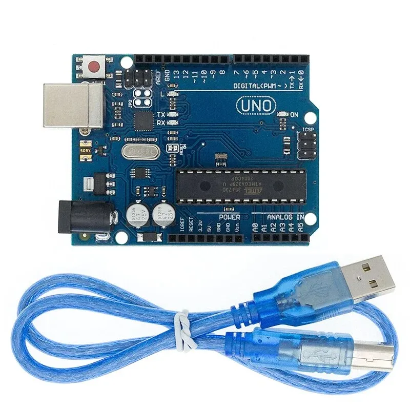
- USB Connectivity: Includes a USB connection for easy programming and uploading of code to the board from your computer.
- ATmega16U4 Microcontroller: Acts as the USB-to-serial converter, enabling direct USB communication with your computer without the need for external components.
- Compatibility: Works seamlessly with Arduino software and programming language, making it beginner-friendly and easy to get started.
- Community Support: Being a popular Arduino board, it has a large community of users, providing a wealth of resources, tutorials, and libraries to help you in your projects.
- Versatility: Suitable for beginners and hobbyists interested in creating interactive projects and prototyping various electronic devices.
Principle of Work:
the Arduino UNO R3 ATmega328 - ATmega16U4 (Compatible) works by executing code written in the Arduino IDE on the ATmega328P microcontroller. The board communicates with a computer via USB, allowing you to upload code and exchange data. By utilizing the I/O pins, you can interface with external components and create interactive projects:
- Microcontroller: The heart of the Arduino UNO is the ATmega328P microcontroller chip. It contains a Central Processing Unit (CPU) that executes instructions and performs calculations, as well as memory (both program memory and data memory) to store code and variables.
- Power Supply: The board can be powered through the USB connection or an external power source, such as a battery or a DC power supply. The voltage is regulated to 5 volts or 3.3 volts, depending on the specific version of the board.
- Input/Output (I/O) Pins: The Arduino UNO has multiple digital and analog I/O pins. These pins can be used for both input and output operations. Digital pins can be set as either HIGH (5V) or LOW (0V), while analog pins can read voltages in a range from 0 to 5V.
- USB-to-Serial Communication: The ATmega16U4 microcontroller on the board acts as a USB-to-serial converter. It enables communication between the Arduino board and a computer through the USB connection. This allows you to upload code, receive data from sensors, and send information to other devices.
- Arduino Software and Programming Language: To program the Arduino UNO, you use the Arduino Software (IDE) on your computer. It provides a simplified programming language based on C/C++, along with a range of libraries and functions that make it easier to control the board's hardware.
- Sketches: In Arduino terminology, programs are called "sketches." You write your code in the Arduino IDE, which includes two main functions: setup() and loop(). The setup() function runs once when the board is powered on or reset, while the loop() function continuously executes in a loop until the board is turned off.
- Uploading Code: After writing your code in the Arduino IDE, you can upload it to the Arduino UNO board using the USB connection. The IDE compiles your code into machine language that the microcontroller can understand and sends it to the board for execution.
- Interaction with Components: By utilizing the digital and analog I/O pins, you can connect various components like LEDs, sensors, motors, and displays to the Arduino UNO. You control these components by writing code that manipulates the I/O pins and interacts with the connected devices.
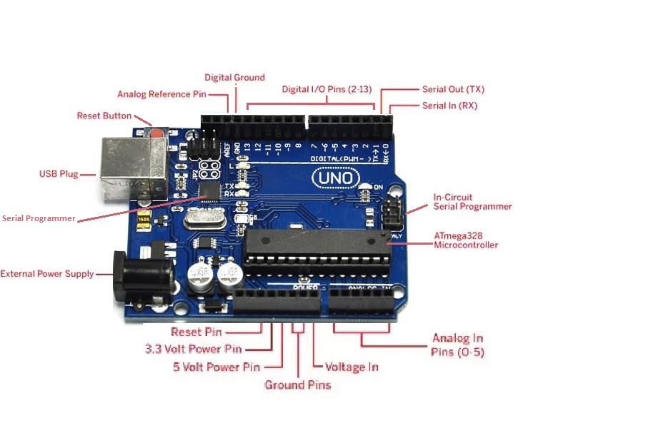
Pinout of the Module:
 Power Supply:
- The Arduino Uno can be powered using either a USB cable or an external power supply. For external power, you can use an AC to DC adapter or a battery. The adapter is connected to the power jack on the Arduino board, while the battery can be connected to the Vin and GND pins on the POWER connector. The recommended voltage range for external power is 7 volts to 12 volts.
Input & Output:
- The Arduino Uno has 14 digital pins that can be used for both input and output operations. You can set the pin mode, write digital values, and read digital values using functions like pinMode(), digitalWrite(), and digitalRead().
- Pin 0 (RX) and Pin 1 (TX) - Serial: These pins are used for transmitting and receiving TTL serial data. They are connected to the ATmega16U4 microcontroller, which handles USB-to-serial communication.
- Pin 2 and Pin 3 - External Interrupts: These pins can be used to trigger an interrupt when there is a low value or a change in value.
- Pins 3, 5, 6, 9, 10, and 11 - PWM: These pins provide 8-bit Pulse Width Modulation (PWM) output using the analogWrite() function.
- SPI Pins (Pin 10 (SS), Pin 11 (MOSI), Pin 12 (MISO), Pin 13 (SCK)): These pins support SPI (Serial Peripheral Interface) communication, although they are not currently included in the Arduino language.
- Pin 13 (LED): This pin is connected to the built-in LED on the board. When the pin is set to HIGH, the LED turns on, and when the pin is set to LOW, the LED turns off.
- Pin 4 (SDA) and Pin 5 (SCL) - I2C: These pins support I2C (Inter-Integrated Circuit) communication using the Wire library.
- AREF (Reference Voltage): AREF is used as a reference voltage for analog inputs with the analogReference() function.
- Reset Pin: The reset pin (RST) is used to reset the microcontroller.
Memory:
- The ATmega328 microcontroller on the Arduino Uno has 32 KB of flash memory for storing code, 2 KB of SRAM for variables and runtime data, and 1 KB of EEPROM for non-volatile data storage.
Communication:
- The Arduino Uno supports UART TTL-serial communication through digital pins TX (1) and RX (0). The Arduino software provides a serial monitor for easy data communication. The board has RX and TX LEDs that blink when data is transmitted or received through the USB connection.
- The SoftwareSerial library allows serial communication on other digital pins, and the ATmega328P microcontroller supports I2C and SPI communication. The Arduino software includes a Wire library to simplify the usage of the I2C bus.
Applications:
- Prototyping and Electronics Projects: The Arduino Uno is widely used for prototyping and building electronic projects. Its versatility and easy-to-use interface make it ideal for beginners and hobbyists to bring their ideas to life.
- Home Automation: The board can be utilized to create home automation systems, enabling control and monitoring of various devices such as lights, appliances, and security systems. With its digital and analog I/O pins, it can interface with sensors, actuators, and communication modules.
- Robotics: Arduino Uno is commonly used in robotics projects to control motors, sensors, and actuators. It provides an excellent platform for building autonomous robots, remote-controlled vehicles, and robotic arms.
- Internet of Things (IoT) Projects: The Arduino Uno can be integrated into IoT projects to connect devices and collect sensor data. With its compatibility with Wi-Fi and Ethernet shields, it can communicate with web servers and cloud platforms, enabling remote monitoring and control.
- Environmental Monitoring: The board can be employed to create environmental monitoring systems. By connecting sensors for temperature, humidity, air quality, and more, it becomes possible to collect data and analyze environmental conditions.
- Wearable Technology: Arduino Uno can be utilized in wearable tech projects to develop interactive garments, smart accessories, and health monitoring devices. Its small size and low power consumption make it suitable for wearable applications.
- Educational Tools: Arduino Uno is widely used in educational settings to teach electronics, programming, and physical computing. Its simplicity and extensive online resources make it an ideal platform for learning the basics of electronics and coding.
- Art and Interactive Installations: Artists and designers often use Arduino Uno to create interactive installations, kinetic sculptures, and interactive artworks. Its ability to control lights, motors, sensors, and displays allows for the creation of immersive and engaging experiences.
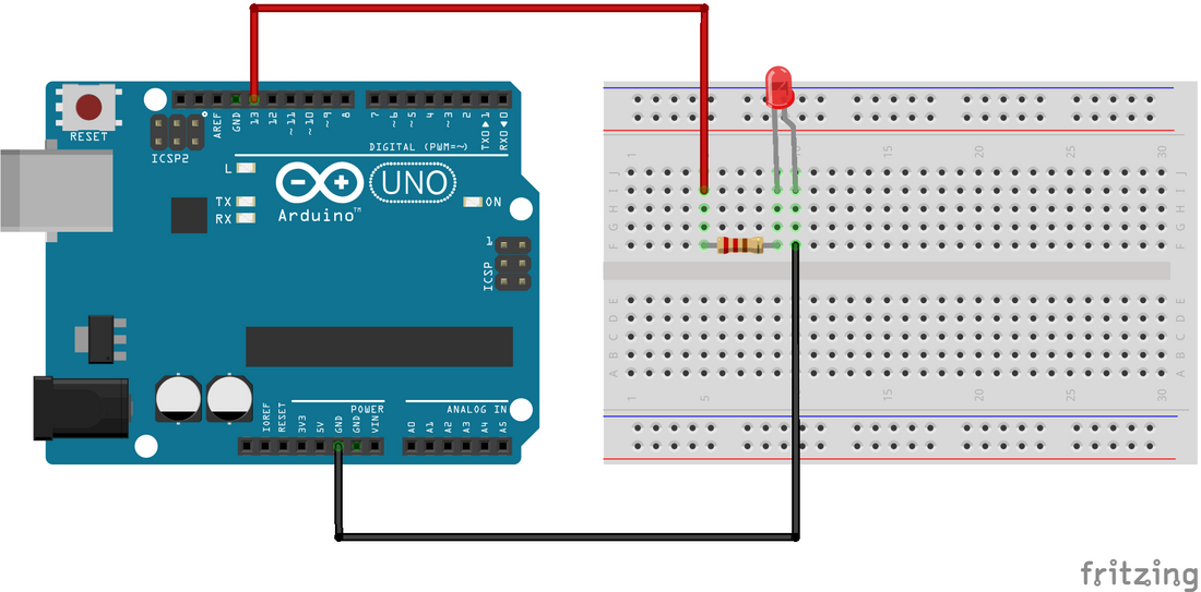
Circuit:
you can rely on the built-in LED on the 13th pin.
Connecting with Arduino for the First Time:
-
Open Arduino IDE: Download the Arduino IDE software from the official website if you haven't already.
-
Connect the Board to Your Computer:
-
Use a USB cable to connect the Arduino board to your computer.
-
Ensure that you use a data USB cable, not a charge-only cable.
-
The cable should have connectors that fit both the board and your computer.
-
-
Select the Board:
-
Click on "Tools" in the menu bar of the Arduino IDE.
-
Locate the "Board" option and click on it.
-
A list of installed board packages will be displayed.
-
Choose the appropriate board for your project by clicking on it.
-
-
Select the Port:
-
In the Arduino IDE, click on "Tools" again.
-
Find the "Port" option and click on it.
-
The available ports will be shown.
-
Look for the port that corresponds to your Arduino board.
-
The port name may vary depending on your operating system.
-
Select the port associated with your Arduino board.
-
-
Upload a Sketch:
-
Write your own Arduino sketch or use an example sketch provided by Arduino (e.g., Blink).
-
Click the "Verify" button to check for errors in your code.
-
If there are no errors, click the "Upload" button to program the board with the sketch.
-
The sketch will start running on the board, and it will run again each time the board is reset.
-
Code:
We'll use the built-in "Blink" example sketch, which makes an LED connected to Pin 13 of the Arduino board blink:
- Go to "File" → "Examples" → "01. Basics" → "Blink" to open the Blink example sketch or just copy the next code.
- Once the sketch is opened or copied, click the "Verify" button (checkmark icon) to compile the code and check for any errors.
- If the compilation is successful, click the "Upload" button (arrow icon) to upload the sketch to your Arduino board.
- The LED on Pin 13 should start blinking once the upload is complete.
void setup() {
 pinMode(13, OUTPUT); // Set Pin 13 as an output
}
void loop() {
 digitalWrite(13, HIGH); // Turn on the LED
 delay(1000); // Wait for 1 second
 digitalWrite(13, LOW); // Turn off the LED
 delay(1000); // Wait for 1 second
}
- In the provided code, the
setup()function is responsible for initializing the Pin 13 as an output pin using thepinMode()function. Theloop()function is where the main logic of the program resides and is executed repeatedly. - Inside the
loop()function, thedigitalWrite()function is used to turn on and off the LED connected to Pin 13. By setting the pin toHIGH, the LED turns on, and by setting it toLOW, the LED turns off. Thedelay()function is used to pause the execution for a specified duration in milliseconds, creating a blinking effect.
Technical Details:
- ATmega328 microcontroller
- Input voltage - 7-12V
- 14 Digital I/O Pins (6 PWM outputs)
- 6 Analog Inputs
- 32k Flash Memory
- 16Mhz Clock Speed
- Operating Voltage: 5 Volt
- Input Voltage: 7 to 20 Volts
- DC Current per I/O Pin: 20 mA
- DC Current for 3.3V Pin: 50 mA
- Clock Speed: 16 MHz
- Length: 68.6 mm
- Width: 53.4 mm
- Weight: 25 g
Resources:
Comparisons:
When comparing the Arduino UNO R3 ATmega328 - ATmega16U4 (Compatible) board with the Arduino UNO SMD CH340 Clone board available on our website, we can observe the following differences:
- Serial Converter IC: The compatible board features the ATmega16U2 as the serial converter, which does not require a separate driver. On the other hand, the SMD version utilizes the CH340, which requires a third-party driver. This distinction can be slightly inconvenient for beginners who may find the additional driver installation process cumbersome.
- Pin Header Configuration: The SMD version of the board offers a notable advantage in terms of pin headers. It provides double pin headers for every pin, allowing you to connect components using either female or male pins. This flexibility offers convenience when working with different types of connectors or devices.
- While both boards serve as compatible alternatives to the original Arduino UNO, the specific differences lie in the serial converter IC and the pin header configuration. The compatible board eliminates the need for a separate driver due to the ATmega16U2, while the SMD version offers enhanced versatility in pin connection options with its double-pin headers. Consider your specific requirements and preferences when choosing between the two boards.
Features:
- Microcontroller: Based on the ATmega328P microcontroller chip.
- Digital Input/Output Pins: 14 digital I/O pins that can be used for interfacing with various components.
- PWM (Pulse Width Modulation) Outputs: 6 of the digital pins can be used as PWM outputs for controlling devices such as motors and LEDs.
- Analog Input Pins: 6 analog input pins for reading analog signals from sensors or potentiometers.
- 16MHz Quartz Crystal Oscillator: Provides precise timing for the microcontroller.
- USB Connectivity: Includes a USB connection for easy programming and uploading of code to the board from your computer.
- ATmega16U4 Microcontroller: Acts as the USB-to-serial converter, enabling direct USB communication with your computer without the need for external components.
- Compatibility: Works seamlessly with Arduino software and programming language, making it beginner-friendly and easy to get started.
- Community Support: Being a popular Arduino board, it has a large community of users, providing a wealth of resources, tutorials, and libraries to help you in your projects.
- Versatility: Suitable for beginners and hobbyists interested in creating interactive projects and prototyping various electronic devices.
Principle of Work:
the Arduino UNO R3 ATmega328 - ATmega16U4 (Compatible) works by executing code written in the Arduino IDE on the ATmega328P microcontroller. The board communicates with a computer via USB, allowing you to upload code and exchange data. By utilizing the I/O pins, you can interface with external components and create interactive projects:
- Microcontroller: The heart of the Arduino UNO is the ATmega328P microcontroller chip. It contains a Central Processing Unit (CPU) that executes instructions and performs calculations, as well as memory (both program memory and data memory) to store code and variables.
- Power Supply: The board can be powered through the USB connection or an external power source, such as a battery or a DC power supply. The voltage is regulated to 5 volts or 3.3 volts, depending on the specific version of the board.
- Input/Output (I/O) Pins: The Arduino UNO has multiple digital and analog I/O pins. These pins can be used for both input and output operations. Digital pins can be set as either HIGH (5V) or LOW (0V), while analog pins can read voltages in a range from 0 to 5V.
- USB-to-Serial Communication: The ATmega16U4 microcontroller on the board acts as a USB-to-serial converter. It enables communication between the Arduino board and a computer through the USB connection. This allows you to upload code, receive data from sensors, and send information to other devices.
- Arduino Software and Programming Language: To program the Arduino UNO, you use the Arduino Software (IDE) on your computer. It provides a simplified programming language based on C/C++, along with a range of libraries and functions that make it easier to control the board's hardware.
- Sketches: In Arduino terminology, programs are called "sketches." You write your code in the Arduino IDE, which includes two main functions: setup() and loop(). The setup() function runs once when the board is powered on or reset, while the loop() function continuously executes in a loop until the board is turned off.
- Uploading Code: After writing your code in the Arduino IDE, you can upload it to the Arduino UNO board using the USB connection. The IDE compiles your code into machine language that the microcontroller can understand and sends it to the board for execution.
- Interaction with Components: By utilizing the digital and analog I/O pins, you can connect various components like LEDs, sensors, motors, and displays to the Arduino UNO. You control these components by writing code that manipulates the I/O pins and interacts with the connected devices.
Pinout of the Module:
Power Supply:
- The Arduino Uno can be powered using either a USB cable or an external power supply. For external power, you can use an AC to DC adapter or a battery. The adapter is connected to the power jack on the Arduino board, while the battery can be connected to the Vin and GND pins on the POWER connector. The recommended voltage range for external power is 7 volts to 12 volts.
Input & Output:
- The Arduino Uno has 14 digital pins that can be used for both input and output operations. You can set the pin mode, write digital values, and read digital values using functions like pinMode(), digitalWrite(), and digitalRead().
- Pin 0 (RX) and Pin 1 (TX) - Serial: These pins are used for transmitting and receiving TTL serial data. They are connected to the ATmega16U4 microcontroller, which handles USB-to-serial communication.
- Pin 2 and Pin 3 - External Interrupts: These pins can be used to trigger an interrupt when there is a low value or a change in value.
- Pins 3, 5, 6, 9, 10, and 11 - PWM: These pins provide 8-bit Pulse Width Modulation (PWM) output using the analogWrite() function.
- SPI Pins (Pin 10 (SS), Pin 11 (MOSI), Pin 12 (MISO), Pin 13 (SCK)): These pins support SPI (Serial Peripheral Interface) communication, although they are not currently included in the Arduino language.
- Pin 13 (LED): This pin is connected to the built-in LED on the board. When the pin is set to HIGH, the LED turns on, and when the pin is set to LOW, the LED turns off.
- Pin 4 (SDA) and Pin 5 (SCL) - I2C: These pins support I2C (Inter-Integrated Circuit) communication using the Wire library.
- AREF (Reference Voltage): AREF is used as a reference voltage for analog inputs with the analogReference() function.
- Reset Pin: The reset pin (RST) is used to reset the microcontroller.
Memory:
- The ATmega328 microcontroller on the Arduino Uno has 32 KB of flash memory for storing code, 2 KB of SRAM for variables and runtime data, and 1 KB of EEPROM for non-volatile data storage.
Communication:
- The Arduino Uno supports UART TTL-serial communication through digital pins TX (1) and RX (0). The Arduino software provides a serial monitor for easy data communication. The board has RX and TX LEDs that blink when data is transmitted or received through the USB connection.
- The SoftwareSerial library allows serial communication on other digital pins, and the ATmega328P microcontroller supports I2C and SPI communication. The Arduino software includes a Wire library to simplify the usage of the I2C bus.
Applications:
- Prototyping and Electronics Projects: The Arduino Uno is widely used for prototyping and building electronic projects. Its versatility and easy-to-use interface make it ideal for beginners and hobbyists to bring their ideas to life.
- Home Automation: The board can be utilized to create home automation systems, enabling control and monitoring of various devices such as lights, appliances, and security systems. With its digital and analog I/O pins, it can interface with sensors, actuators, and communication modules.
- Robotics: Arduino Uno is commonly used in robotics projects to control motors, sensors, and actuators. It provides an excellent platform for building autonomous robots, remote-controlled vehicles, and robotic arms.
- Internet of Things (IoT) Projects: The Arduino Uno can be integrated into IoT projects to connect devices and collect sensor data. With its compatibility with Wi-Fi and Ethernet shields, it can communicate with web servers and cloud platforms, enabling remote monitoring and control.
- Environmental Monitoring: The board can be employed to create environmental monitoring systems. By connecting sensors for temperature, humidity, air quality, and more, it becomes possible to collect data and analyze environmental conditions.
- Wearable Technology: Arduino Uno can be utilized in wearable tech projects to develop interactive garments, smart accessories, and health monitoring devices. Its small size and low power consumption make it suitable for wearable applications.
- Educational Tools: Arduino Uno is widely used in educational settings to teach electronics, programming, and physical computing. Its simplicity and extensive online resources make it an ideal platform for learning the basics of electronics and coding.
- Art and Interactive Installations: Artists and designers often use Arduino Uno to create interactive installations, kinetic sculptures, and interactive artworks. Its ability to control lights, motors, sensors, and displays allows for the creation of immersive and engaging experiences.
Circuit:
you can rely on the built-in LED on the 13th pin.
Connecting with Arduino for the First Time:
-
Open Arduino IDE: Download the Arduino IDE software from the official website if you haven't already.
-
Connect the Board to Your Computer:
-
Use a USB cable to connect the Arduino board to your computer.
-
Ensure that you use a data USB cable, not a charge-only cable.
-
The cable should have connectors that fit both the board and your computer.
-
-
Select the Board:
-
Click on "Tools" in the menu bar of the Arduino IDE.
-
Locate the "Board" option and click on it.
-
A list of installed board packages will be displayed.
-
Choose the appropriate board for your project by clicking on it.
-
-
Select the Port:
-
In the Arduino IDE, click on "Tools" again.
-
Find the "Port" option and click on it.
-
The available ports will be shown.
-
Look for the port that corresponds to your Arduino board.
-
The port name may vary depending on your operating system.
-
Select the port associated with your Arduino board.
-
-
Upload a Sketch:
-
Write your own Arduino sketch or use an example sketch provided by Arduino (e.g., Blink).
-
Click the "Verify" button to check for errors in your code.
-
If there are no errors, click the "Upload" button to program the board with the sketch.
-
The sketch will start running on the board, and it will run again each time the board is reset.
-
Code:
We'll use the built-in "Blink" example sketch, which makes an LED connected to Pin 13 of the Arduino board blink:
- Go to "File" → "Examples" → "01. Basics" → "Blink" to open the Blink example sketch or just copy the next code.
- Once the sketch is opened or copied, click the "Verify" button (checkmark icon) to compile the code and check for any errors.
- If the compilation is successful, click the "Upload" button (arrow icon) to upload the sketch to your Arduino board.
- The LED on Pin 13 should start blinking once the upload is complete.
void setup() {
 pinMode(13, OUTPUT); // Set Pin 13 as an output
}
void loop() {
 digitalWrite(13, HIGH); // Turn on the LED
 delay(1000); // Wait for 1 second
 digitalWrite(13, LOW); // Turn off the LED
 delay(1000); // Wait for 1 second
}
- In the provided code, the
setup()function is responsible for initializing the Pin 13 as an output pin using thepinMode()function. Theloop()function is where the main logic of the program resides and is executed repeatedly. - Inside the
loop()function, thedigitalWrite()function is used to turn on and off the LED connected to Pin 13. By setting the pin toHIGH, the LED turns on, and by setting it toLOW, the LED turns off. Thedelay()function is used to pause the execution for a specified duration in milliseconds, creating a blinking effect.
Technical Details:
- ATmega328 microcontroller
- Input voltage - 7-12V
- 14 Digital I/O Pins (6 PWM outputs)
- 6 Analog Inputs
- 32k Flash Memory
- 16Mhz Clock Speed
- Operating Voltage: 5 Volt
- Input Voltage: 7 to 20 Volts
- DC Current per I/O Pin: 20 mA
- DC Current for 3.3V Pin: 50 mA
- Clock Speed: 16 MHz
- Length: 68.6 mm
- Width: 53.4 mm
- Weight: 25 g
Resources:
Comparisons:
When comparing the Arduino UNO R3 ATmega328 - ATmega16U4 (Compatible) board with the Arduino UNO SMD CH340 Clone board available on our website, we can observe the following differences:
- Serial Converter IC: The compatible board features the ATmega16U2 as the serial converter, which does not require a separate driver. On the other hand, the SMD version utilizes the CH340, which requires a third-party driver. This distinction can be slightly inconvenient for beginners who may find the additional driver installation process cumbersome.
- Pin Header Configuration: The SMD version of the board offers a notable advantage in terms of pin headers. It provides double pin headers for every pin, allowing you to connect components using either female or male pins. This flexibility offers convenience when working with different types of connectors or devices.
- While both boards serve as compatible alternatives to the original Arduino UNO, the specific differences lie in the serial converter IC and the pin header configuration. The compatible board eliminates the need for a separate driver due to the ATmega16U2, while the SMD version offers enhanced versatility in pin connection options with its double-pin headers. Consider your specific requirements and preferences when choosing between the two boards.