Specifications:
- Dimensions: 32 x 24 x 12 mm
- Weight: 3.06 g
- Material: FR4
- Working Voltage: 5V
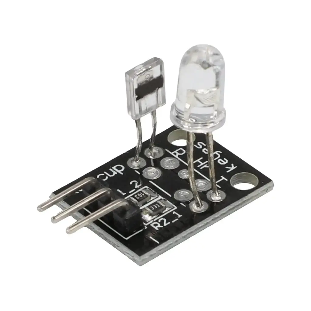
- Sensing Method: IR LED + Phototransistor
- Application: Teaching experiments and basic pulse detection
Pinout of the Module:
| Pin |
Description |
| (-) |
GND |
| Middle Pin |
+5V |
| S |
Analog Signal Output |
Working Principle:
The module emits infrared light through the fingertip using the onboard IR LED. A phototransistor on the opposite side detects the amount of light transmitted. Blood pulses through the finger with each heartbeat, absorbing more or less IR light and causing a measurable change in the phototransistor's output. This fluctuation can be read by a microcontroller's analog pin.
The circuit should be isolated from ambient light sources, especially 50/60 Hz lighting, to avoid interference. Sensitivity can be adjusted by changing resistor values experimentally.
Connecting to Arduino:
- S → A0 (Analog input pin)
- Middle pin (+) → 5V
- (-) → GND
Code Example:
int sensorPin = 0;
double alpha = 0.75;
int period = 100;
double change = 0.0;
double minval = 0.0;

void setup() {
  Serial.begin(9600);
}

void loop() {
  static double oldValue = 0;
  static double oldchange = 0;
  int rawValue = analogRead(sensorPin);
  double value = alpha * oldValue + (1 - alpha) * rawValue;
  Serial.print(rawValue);
  Serial.print(",");
  Serial.println(value);
  oldValue = value;
  delay(period);
}
How It Works:
- Reads analog signal from the KY-039's S pin connected to A0.
- Applies a low-pass filter using the
alpha smoothing factor to eliminate noise.
- Prints both raw and smoothed values to the Serial Monitor for monitoring pulse fluctuations.
- Delays for 100ms between each read to allow stabilization.
Applications:
- Basic pulse rate measurement
- Educational demonstrations of IR sensing
- Arduino and microcontroller experimentation
- DIY heartbeat visualizers
Package Includes:
- 1 x KY-039 Heartbeat Sensor Module
Specifications:
- Dimensions: 32 x 24 x 12 mm
- Weight: 3.06 g
- Material: FR4
- Working Voltage: 5V
- Sensing Method: IR LED + Phototransistor
- Application: Teaching experiments and basic pulse detection
Pinout of the Module:
| Pin |
Description |
| (-) |
GND |
| Middle Pin |
+5V |
| S |
Analog Signal Output |
Working Principle:
The module emits infrared light through the fingertip using the onboard IR LED. A phototransistor on the opposite side detects the amount of light transmitted. Blood pulses through the finger with each heartbeat, absorbing more or less IR light and causing a measurable change in the phototransistor's output. This fluctuation can be read by a microcontroller's analog pin.
The circuit should be isolated from ambient light sources, especially 50/60 Hz lighting, to avoid interference. Sensitivity can be adjusted by changing resistor values experimentally.
Connecting to Arduino:
- S → A0 (Analog input pin)
- Middle pin (+) → 5V
- (-) → GND
Code Example:
int sensorPin = 0;
double alpha = 0.75;
int period = 100;
double change = 0.0;
double minval = 0.0;

void setup() {
  Serial.begin(9600);
}

void loop() {
  static double oldValue = 0;
  static double oldchange = 0;
  int rawValue = analogRead(sensorPin);
  double value = alpha * oldValue + (1 - alpha) * rawValue;
  Serial.print(rawValue);
  Serial.print(",");
  Serial.println(value);
  oldValue = value;
  delay(period);
}
How It Works:
- Reads analog signal from the KY-039's S pin connected to A0.
- Applies a low-pass filter using the
alpha smoothing factor to eliminate noise.
- Prints both raw and smoothed values to the Serial Monitor for monitoring pulse fluctuations.
- Delays for 100ms between each read to allow stabilization.
Applications:
- Basic pulse rate measurement
- Educational demonstrations of IR sensing
- Arduino and microcontroller experimentation
- DIY heartbeat visualizers
Package Includes:
- 1 x KY-039 Heartbeat Sensor Module