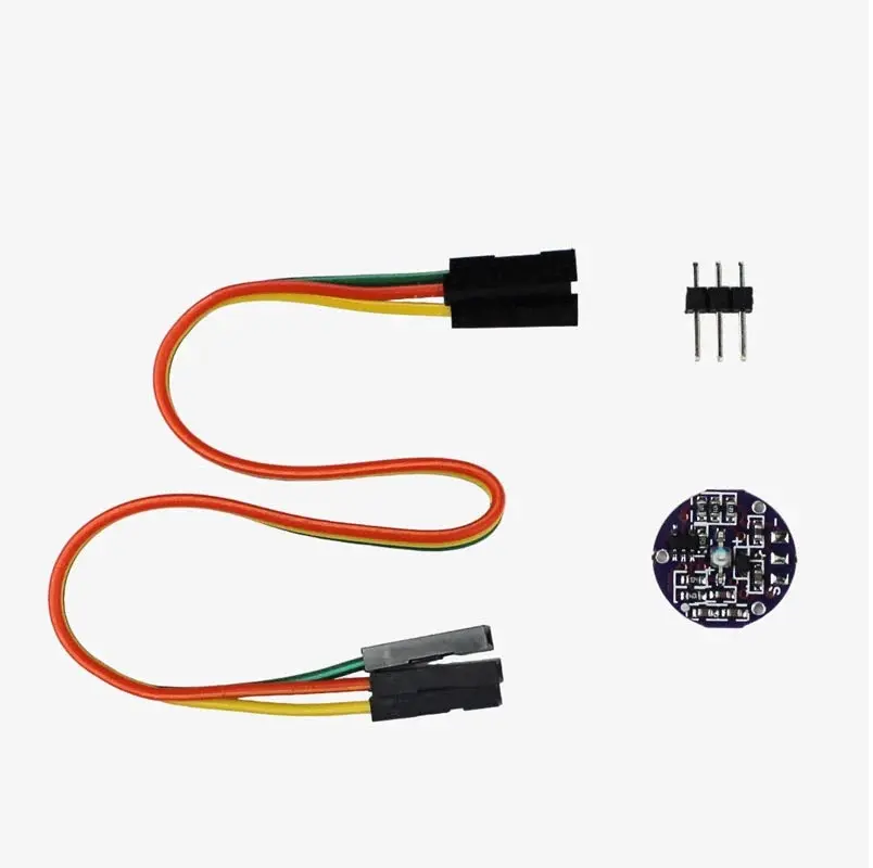
Heart Rate Pulse Sensor Module Unsoldered Wire
The Pulse Sensor is an Arduino-compatible heart-rate sensor designed for easy integration into a wide range of projects. Featuring an integrated optical amplifying and noise elimination circuit, it ensures accurate readings. Ideal for students, developers, athletes, and hobbyists, this plug-and-play module provides real-time heart rate data. Simply clip the sensor to your earlobe or fingertip and connect it to your Arduino.
Package Includes:
- 1 x Heart Rate Pulse Sensor Module (Unsoldered Wire)
Features:
- Accurate Heart Rate Monitoring: Uses optical sensing to provide real-time heart rate data with high reliability.
- Plug-and-Play Compatibility: Easily integrates with Arduino and other microcontrollers without the need for complex wiring.
- Compact and Versatile: Ideal for wearables, fitness trackers, and health monitoring systems.
- Low Power Consumption: Suitable for battery-powered applications with efficient energy usage.
- Integrated Amplification and Noise Filtering: Enhances measurement accuracy by minimizing interference.
- User-Friendly Design: Heart logo guides finger placement. Green LED and ambient light sensor improve signal detection.
- Reverse Protection Diode: Protects the module from damage due to reverse polarity connections.
Principle of Work:
- Optical Sensing: Infrared light emitted into the skin reflects changes in blood volume back to a photodiode.
- Blood Volume Changes: Light absorption fluctuates with each heartbeat, affecting the reflected light intensity.
- Amplification and Filtering: Internal circuits amplify the signal and reduce external noise.
- Signal Processing: The signal is processed to extract real-time heart rate information.
- Output: Analog output is sent to a microcontroller for data display or transmission.
Pinout of the Module:

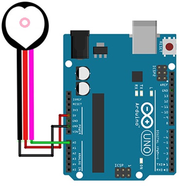
- VCC: Connect to 3.3V or 5V power supply
- GND: Connect to ground
- Signal: Analog output to microcontroller (e.g. A0)
Applications:
- Wearable fitness devices and trackers
- Medical monitoring (e.g. patient heart rate monitoring)
- Biometric authentication systems
- Emotion and stress detection
- Human-computer interaction and research
- Gaming and VR-based physiological feedback
- IoT health monitoring systems
Circuit Diagram:
Library:
No external library required.
Arduino Code:
const int PulseSensorPurplePin = A0; // Pulse sensor connected to A0
const int LED13 = 13; // On-board LED
int Signal; // To store raw pulse data
const int Threshold = 550;

void setup() {
  pinMode(LED13, OUTPUT);
  Serial.begin(9600);
}

void loop() {
  Signal = analogRead(PulseSensorPurplePin);
  Serial.println(Signal);

  if (Signal > Threshold) {
    digitalWrite(LED13, HIGH);
  } else {
    digitalWrite(LED13, LOW);
  }

  delay(10);
}
How It Works (Code Explanation):
- Reads analog data from the sensor via pin A0.
- Prints raw signal to the Serial Monitor or Plotter.
- Turns on the LED if the signal exceeds the threshold (heartbeat detected).
- Turns off the LED otherwise.
- Includes a short delay for smooth performance.
Technical Details:
- Dimensions: 16mm diameter, 3mm thickness
- Operating Voltage: 3–5V
- Current Draw: 4 mA at 5V
- Cable Length: 18 cm
- Connections: VCC, GND, Signal (Analog Out)
Comparisons:
| Feature | Pulse Sensor | AD8232 ECG Module |
|---|---|---|
| Functionality | Heart Rate Monitoring | Heart Rate + ECG |
| Sensing Technology | Optical (IR + Photodiode) | Electrode Pads (ECG) |
| Output | Analog Voltage | Digital ECG Signal |
| Signal Processing | Basic Amplification + Filtering | Advanced ECG Signal Filtering |
| Use Cases | Wearables, DIY Projects | Medical Research, ECG Monitoring |
| Voltage | 3V–5V | Similar (varies slightly) |
Resources:
Features:
- Accurate Heart Rate Monitoring: Uses optical sensing to provide real-time heart rate data with high reliability.
- Plug-and-Play Compatibility: Easily integrates with Arduino and other microcontrollers without the need for complex wiring.
- Compact and Versatile: Ideal for wearables, fitness trackers, and health monitoring systems.
- Low Power Consumption: Suitable for battery-powered applications with efficient energy usage.
- Integrated Amplification and Noise Filtering: Enhances measurement accuracy by minimizing interference.
- User-Friendly Design: Heart logo guides finger placement. Green LED and ambient light sensor improve signal detection.
- Reverse Protection Diode: Protects the module from damage due to reverse polarity connections.
Principle of Work:
- Optical Sensing: Infrared light emitted into the skin reflects changes in blood volume back to a photodiode.
- Blood Volume Changes: Light absorption fluctuates with each heartbeat, affecting the reflected light intensity.
- Amplification and Filtering: Internal circuits amplify the signal and reduce external noise.
- Signal Processing: The signal is processed to extract real-time heart rate information.
- Output: Analog output is sent to a microcontroller for data display or transmission.
Pinout of the Module:
- VCC: Connect to 3.3V or 5V power supply
- GND: Connect to ground
- Signal: Analog output to microcontroller (e.g. A0)
Applications:
- Wearable fitness devices and trackers
- Medical monitoring (e.g. patient heart rate monitoring)
- Biometric authentication systems
- Emotion and stress detection
- Human-computer interaction and research
- Gaming and VR-based physiological feedback
- IoT health monitoring systems
Circuit Diagram:
Library:
No external library required.
Arduino Code:
const int PulseSensorPurplePin = A0; // Pulse sensor connected to A0
const int LED13 = 13; // On-board LED
int Signal; // To store raw pulse data
const int Threshold = 550;

void setup() {
  pinMode(LED13, OUTPUT);
  Serial.begin(9600);
}

void loop() {
  Signal = analogRead(PulseSensorPurplePin);
  Serial.println(Signal);

  if (Signal > Threshold) {
    digitalWrite(LED13, HIGH);
  } else {
    digitalWrite(LED13, LOW);
  }

  delay(10);
}
How It Works (Code Explanation):
- Reads analog data from the sensor via pin A0.
- Prints raw signal to the Serial Monitor or Plotter.
- Turns on the LED if the signal exceeds the threshold (heartbeat detected).
- Turns off the LED otherwise.
- Includes a short delay for smooth performance.
Technical Details:
- Dimensions: 16mm diameter, 3mm thickness
- Operating Voltage: 3–5V
- Current Draw: 4 mA at 5V
- Cable Length: 18 cm
- Connections: VCC, GND, Signal (Analog Out)
Comparisons:
| Feature | Pulse Sensor | AD8232 ECG Module |
|---|---|---|
| Functionality | Heart Rate Monitoring | Heart Rate + ECG |
| Sensing Technology | Optical (IR + Photodiode) | Electrode Pads (ECG) |
| Output | Analog Voltage | Digital ECG Signal |
| Signal Processing | Basic Amplification + Filtering | Advanced ECG Signal Filtering |
| Use Cases | Wearables, DIY Projects | Medical Research, ECG Monitoring |
| Voltage | 3V–5V | Similar (varies slightly) |