Features
- 5V DC coil voltage
- 10A switching capacity
- SPDT contact arrangement
- Compact subminiature design
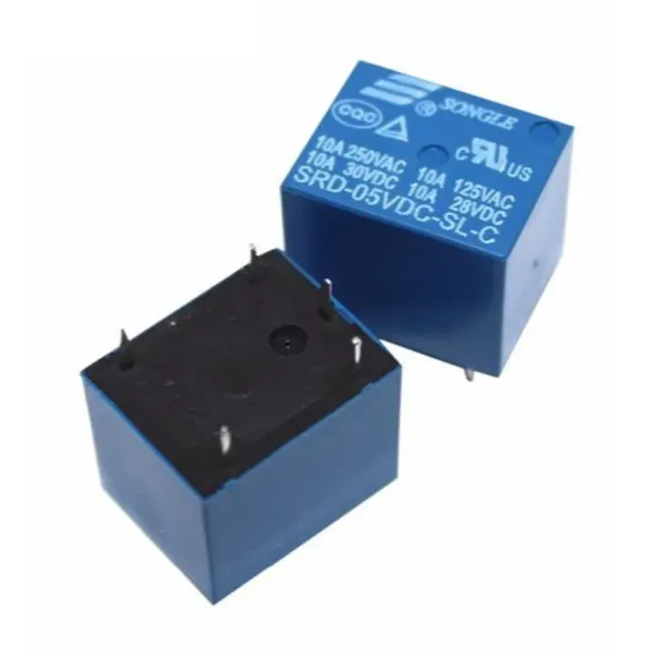
- 5-pin configuration
- Suitable for high-density PCB designs
- Long operational life
- Suitable for AC and DC load switching
- Black housing
Principle of Operation
When 5V DC is applied to the relay coil, an electromagnetic field is generated. This magnetic field moves the internal armature and changes the contact position between COM, NO, and NC.
When the coil is de-energized, the internal spring returns the contacts to their normal position. This allows a low-power control circuit to switch a separate higher-power load.
Pinout

Coil Connections
- Coil End 1: One side of the 5V relay coil.
- Coil End 2: The other side of the 5V relay coil.
Contact Connections
- COM: Common contact connected to the load circuit.
- NC: Normally Closed contact. COM is connected to NC when the relay coil is not energized.
- NO: Normally Open contact. COM is connected to NO when the relay coil is energized.
Wiring
- Connect the 5V relay coil through a suitable transistor or relay driver circuit.
- Connect the control signal from the microcontroller to the driver input.
- Connect the load circuit through COM and either NO or NC.
- Use COM + NO when the load should normally be OFF.
- Use COM + NC when the load should normally be ON.
- For inductive DC loads such as motors, use suitable protection such as a flyback diode.
Circuit
The following example shows a relay being used to control a DC motor. A control signal activates the relay driver, which energizes the relay coil and switches power to the motor.

Library
No special library is required. The relay can be controlled using standard digital output signals when used with a suitable transistor, relay driver, or relay module circuit.
Code
const int relayPin = 3;

void setup() {
pinMode(relayPin, OUTPUT);
digitalWrite(relayPin, LOW);
}

void loop() {
digitalWrite(relayPin, HIGH);  // Relay ON
delay(1000);

digitalWrite(relayPin, LOW);   // Relay OFF
delay(1000);
}
Note: A bare relay coil should not be connected directly to an Arduino GPIO pin. Use a suitable transistor or relay driver circuit with a flyback diode.
Applications
- ON/OFF load switching
- Motor control
- Lighting control
- Home appliances
- Refrigerators and washing machines
- Heating systems and temperature controllers
- Vending machines
- Packaging and molding equipment
- Traffic signal controllers
- Automotive control systems
- Protection and control circuits
- Switching high-power circuits using low-power control signals
Specifications
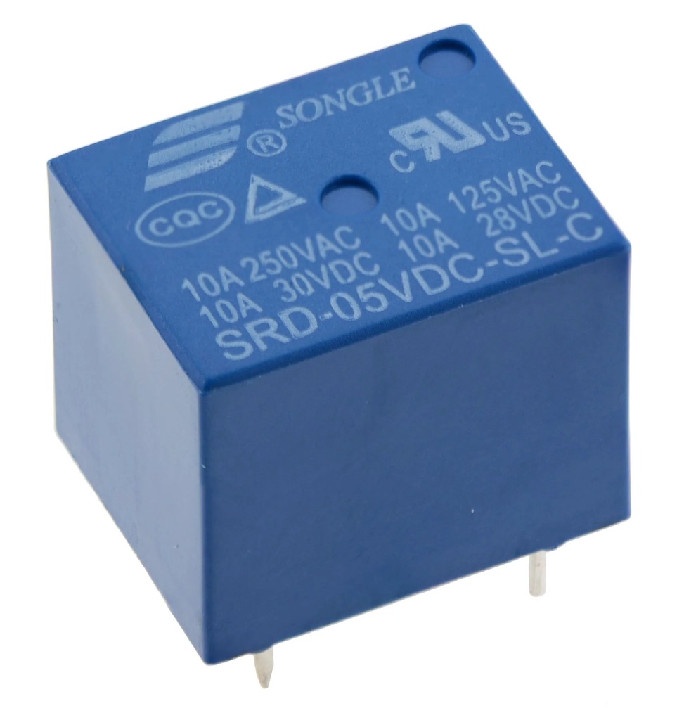
- Model: SRD-05VDC-SL-C
- Coil Voltage: 5V DC
- Number of Pins: 5
- Contact Type: SPDT
- Rated Load: 10A at 250V AC / 10A at 30V DC
- Maximum Switching Current: 10A
- Maximum Switching Voltage: 110V DC / 250V AC
- Coil Power: 0.45W
- Contact Arrangement: 1C (NO/NC)
- Dimensions: 19 x 15 x 15mm
Resources
Comparison
Electromechanical Relay:
- Uses an electromagnetic coil and mechanical contacts.
- Can switch both AC and DC loads.
- Can support relatively high current loads.
- Provides physical isolation between the coil and contacts.
- Has moving parts that can wear over time.
- Produces a mechanical clicking sound during switching.
Solid State Relay:
- Uses semiconductor components instead of mechanical contacts.
- Provides fast and silent switching.
- Has no mechanical contact wear.
- Provides electrical isolation between control and load circuits.
- AC SSRs are generally designed for AC load switching.
Safety
Do not connect the relay coil directly to a microcontroller GPIO pin. Use a suitable driver circuit. When switching mains voltage or high-current loads, use proper insulation, fusing, wiring, and enclosure. Do not exceed the relay contact ratings.
Features
- 5V DC coil voltage
- 10A switching capacity
- SPDT contact arrangement
- Compact subminiature design
- 5-pin configuration
- Suitable for high-density PCB designs
- Long operational life
- Suitable for AC and DC load switching
- Black housing
Principle of Operation
When 5V DC is applied to the relay coil, an electromagnetic field is generated. This magnetic field moves the internal armature and changes the contact position between COM, NO, and NC.
When the coil is de-energized, the internal spring returns the contacts to their normal position. This allows a low-power control circuit to switch a separate higher-power load.
Pinout
Coil Connections
- Coil End 1: One side of the 5V relay coil.
- Coil End 2: The other side of the 5V relay coil.
Contact Connections
- COM: Common contact connected to the load circuit.
- NC: Normally Closed contact. COM is connected to NC when the relay coil is not energized.
- NO: Normally Open contact. COM is connected to NO when the relay coil is energized.
Wiring
- Connect the 5V relay coil through a suitable transistor or relay driver circuit.
- Connect the control signal from the microcontroller to the driver input.
- Connect the load circuit through COM and either NO or NC.
- Use COM + NO when the load should normally be OFF.
- Use COM + NC when the load should normally be ON.
- For inductive DC loads such as motors, use suitable protection such as a flyback diode.
Circuit
The following example shows a relay being used to control a DC motor. A control signal activates the relay driver, which energizes the relay coil and switches power to the motor.
Library
No special library is required. The relay can be controlled using standard digital output signals when used with a suitable transistor, relay driver, or relay module circuit.
Code
const int relayPin = 3;

void setup() {
pinMode(relayPin, OUTPUT);
digitalWrite(relayPin, LOW);
}

void loop() {
digitalWrite(relayPin, HIGH);  // Relay ON
delay(1000);

digitalWrite(relayPin, LOW);   // Relay OFF
delay(1000);
}
Note: A bare relay coil should not be connected directly to an Arduino GPIO pin. Use a suitable transistor or relay driver circuit with a flyback diode.
Applications
- ON/OFF load switching
- Motor control
- Lighting control
- Home appliances
- Refrigerators and washing machines
- Heating systems and temperature controllers
- Vending machines
- Packaging and molding equipment
- Traffic signal controllers
- Automotive control systems
- Protection and control circuits
- Switching high-power circuits using low-power control signals
Specifications
- Model: SRD-05VDC-SL-C
- Coil Voltage: 5V DC
- Number of Pins: 5
- Contact Type: SPDT
- Rated Load: 10A at 250V AC / 10A at 30V DC
- Maximum Switching Current: 10A
- Maximum Switching Voltage: 110V DC / 250V AC
- Coil Power: 0.45W
- Contact Arrangement: 1C (NO/NC)
- Dimensions: 19 x 15 x 15mm
Resources
Comparison
Electromechanical Relay:
- Uses an electromagnetic coil and mechanical contacts.
- Can switch both AC and DC loads.
- Can support relatively high current loads.
- Provides physical isolation between the coil and contacts.
- Has moving parts that can wear over time.
- Produces a mechanical clicking sound during switching.
Solid State Relay:
- Uses semiconductor components instead of mechanical contacts.
- Provides fast and silent switching.
- Has no mechanical contact wear.
- Provides electrical isolation between control and load circuits.
- AC SSRs are generally designed for AC load switching.
Safety
Do not connect the relay coil directly to a microcontroller GPIO pin. Use a suitable driver circuit. When switching mains voltage or high-current loads, use proper insulation, fusing, wiring, and enclosure. Do not exceed the relay contact ratings.