Features:
- High DC gain for amplifying a small base current to a larger collector current.
- High collector-emitter voltage rating of 60V.
- Collector current up to 5A for high-current applications.
- Darlington configuration with a low base current requirement.
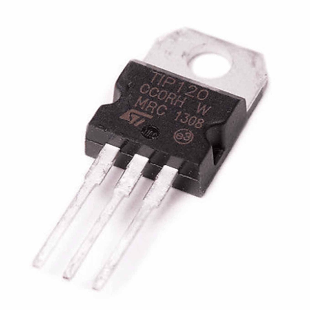
- TO-220 package is suitable for mounting on heat sinks.
- Fast switching speed.
- Low saturation voltage for reduced power dissipation.
- Wide operating temperature range: -65°C to 150°C.
Principle of Work:
The TIP120 has two NPN transistors connected in Darlington configuration. A small base current turns on the first transistor, which then drives the second transistor, allowing a much larger current to flow from collector to emitter. It operates as a switch (fully ON or OFF) or as an amplifier controlling current flow. Typical base current to fully turn on is around 5mA, often provided via an Arduino digital pin through a resistor.
Pinout:
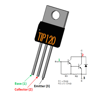
- Base (B): Input pin controlling the transistor switching.
- Collector (C): Output pin connected to the load.
- Emitter (E): Ground pin connected to the negative side of the load.
Applications:
- Motor control – speed and direction of DC motors.
- Relay control – switching relays on/off.
- LED brightness control.
- Audio amplification.
- Power switching for heaters, pumps, solenoids, and other high-power devices.
Circuit Example:
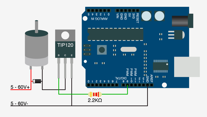
Connect the motor between the power supply and the collector. The emitter connects to ground. Use a diode across the motor terminals as a flyback diode. The base connects to Arduino pin 9 via a 2.2k resistor.
Library:
No library required.
Example Arduino Code:
int motorPin = 9;  // Motor control pin
int speed = 0;

void setup() {
  pinMode(motorPin, OUTPUT);
  Serial.begin(9600);
}

void loop() {
  if (Serial.available() > 0) {
    speed = Serial.parseInt();
    speed = map(speed, 0, 100, 0, 255);
    analogWrite(motorPin, speed);
  }
}
This code reads a speed value (0-100) from the serial monitor, maps it to PWM range (0-255), and controls the motor speed accordingly.
Technical Details:
- NPN Medium-power Darlington Transistor
- High DC Current Gain (hFE), typically 1000
- Continuous Collector Current (IC): 5A
- Collector-Emitter Voltage (VCE): 60V
- Collector-Base Voltage (VCB): 60V
- Emitter-Base Voltage (VBE): 5V
- Base Current (IB): 120mA max
- Peak Load Current: 8A
- Package: TO-220
Resources:
Comparisons:
The TIP120 and IRFZ44NPBF MOSFET differ in several key parameters:
- Voltage rating: TIP120 (60V) higher than IRFZ44NPBF (55V).
- Current rating: IRFZ44NPBF (49A) much higher than TIP120 (5A).
- Gate threshold voltage: IRFZ44NPBF lower (2V) vs TIP120 (2.5V).
- Control signal: TIP120 requires base current (BJT), IRFZ44NPBF is voltage controlled (MOSFET).
- Heat dissipation: IRFZ44NPBF has lower on-resistance, dissipates less heat.
TIP120 is better for high-voltage switching with moderate current; IRFZ44NPBF suits high-current, low-voltage control with lower losses.
Features:
- High DC gain for amplifying a small base current to a larger collector current.
- High collector-emitter voltage rating of 60V.
- Collector current up to 5A for high-current applications.
- Darlington configuration with a low base current requirement.
- TO-220 package is suitable for mounting on heat sinks.
- Fast switching speed.
- Low saturation voltage for reduced power dissipation.
- Wide operating temperature range: -65°C to 150°C.
Principle of Work:
The TIP120 has two NPN transistors connected in Darlington configuration. A small base current turns on the first transistor, which then drives the second transistor, allowing a much larger current to flow from collector to emitter. It operates as a switch (fully ON or OFF) or as an amplifier controlling current flow. Typical base current to fully turn on is around 5mA, often provided via an Arduino digital pin through a resistor.
Pinout:
- Base (B): Input pin controlling the transistor switching.
- Collector (C): Output pin connected to the load.
- Emitter (E): Ground pin connected to the negative side of the load.
Applications:
- Motor control – speed and direction of DC motors.
- Relay control – switching relays on/off.
- LED brightness control.
- Audio amplification.
- Power switching for heaters, pumps, solenoids, and other high-power devices.
Circuit Example:
Connect the motor between the power supply and the collector. The emitter connects to ground. Use a diode across the motor terminals as a flyback diode. The base connects to Arduino pin 9 via a 2.2k resistor.
Library:
No library required.
Example Arduino Code:
int motorPin = 9;  // Motor control pin
int speed = 0;

void setup() {
  pinMode(motorPin, OUTPUT);
  Serial.begin(9600);
}

void loop() {
  if (Serial.available() > 0) {
    speed = Serial.parseInt();
    speed = map(speed, 0, 100, 0, 255);
    analogWrite(motorPin, speed);
  }
}
This code reads a speed value (0-100) from the serial monitor, maps it to PWM range (0-255), and controls the motor speed accordingly.
Technical Details:
- NPN Medium-power Darlington Transistor
- High DC Current Gain (hFE), typically 1000
- Continuous Collector Current (IC): 5A
- Collector-Emitter Voltage (VCE): 60V
- Collector-Base Voltage (VCB): 60V
- Emitter-Base Voltage (VBE): 5V
- Base Current (IB): 120mA max
- Peak Load Current: 8A
- Package: TO-220
Resources:
Comparisons:
The TIP120 and IRFZ44NPBF MOSFET differ in several key parameters:
- Voltage rating: TIP120 (60V) higher than IRFZ44NPBF (55V).
- Current rating: IRFZ44NPBF (49A) much higher than TIP120 (5A).
- Gate threshold voltage: IRFZ44NPBF lower (2V) vs TIP120 (2.5V).
- Control signal: TIP120 requires base current (BJT), IRFZ44NPBF is voltage controlled (MOSFET).
- Heat dissipation: IRFZ44NPBF has lower on-resistance, dissipates less heat.
TIP120 is better for high-voltage switching with moderate current; IRFZ44NPBF suits high-current, low-voltage control with lower losses.