- All products
- Sensors & Modules
- LED Module
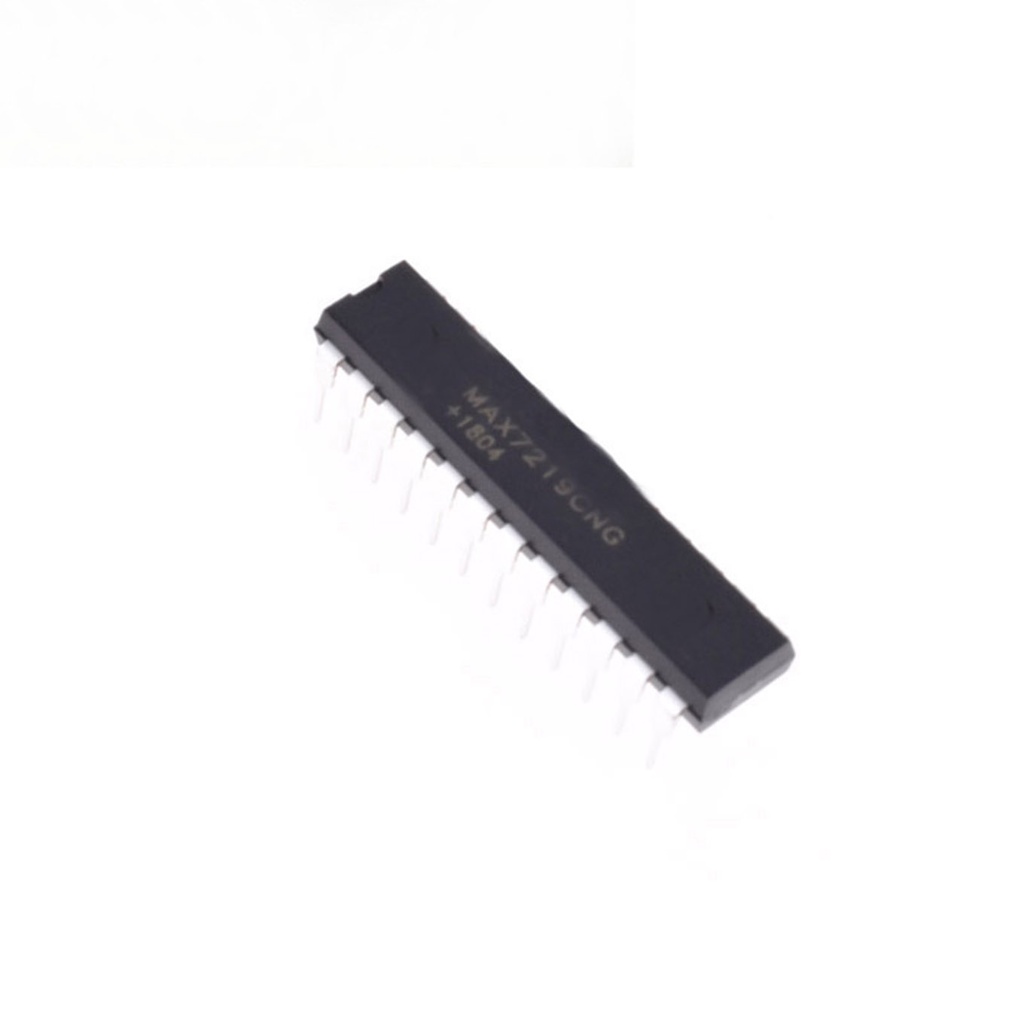
- IC LED Display Driver MAX7219 8-Digit DIP24
- LED Module
Features:
- Serial Interface (SPI): Allows communication with microcontrollers using just three wires.
- Common-Cathode Support: Drives 7-segment displays, bar-graphs, or individual LEDs.
- On-chip BCD Code-B Decoder simplifies numeric display control.
- 8x8 Static RAM: Stores the data for each digit/segment.
- Scan Limit Register: Displays 1 to 8 digits.
- Current Control: Set segment current with a single external resistor.
- Low-Power Shutdown Mode: Reduces current draw to 150μA.
- Brightness Control: Both analog and digital options.
- Test Mode: Forces all LEDs ON for debugging.
Technical Specifications:
- Supply Voltage: 4V to 5.5V
- Max Output Current: 40mA per segment
- Max SPI Clock Frequency: 10MHz
- Shutdown Mode Current: 150μA
- Package: DIP-24
Principle of Work:
The MAX7219 uses a multiplexing method to scan and light up each digit or LED segment rapidly, giving the illusion of a continuous display. It receives data via the SPI interface and stores it in internal RAM, allowing individual digits to be addressed and updated. Brightness can be adjusted with digital commands or by changing the external resistor value on the ISET pin.
Pinout:
- V+: Power Supply (4V–5.5V)
- GND: Ground
- DIN: Serial Data Input
- CS (LOAD): Chip Select
- CLK: Serial Clock
- DOUT: Serial Data Output (for cascading)
- DIG0–DIG7: Digit (common cathode) outputs
- SEG A–G, DP: Segment driver outputs
- ISET: Segment current setting (via external resistor)
- BI/RBO: Blank input / Ripple blank output
Applications:
- Digital clocks
- Scoreboards
- Temperature displays
- Audio level meters
- Industrial panel indicators
- Electronic signage
Example Circuit:
This digital clock circuit uses an Arduino UNO, a MAX7219, and six 7-segment displays to show time. Push buttons allow mode switching and time setting.
Library:
No additional library is needed. Communicates over standard SPI protocol.
Code Example:
This code initializes the display, handles SPI communication, and updates the time. Push buttons allow changing modes and setting time values (seconds, minutes, hours).
#include "SPI.h"
int SPI_MOSI = 12;
int SPI_CLK = 11;
int SPI_CS = 10;
byte spidata[16];
uint8_t sec = 0, minute = 0, hour = 12;
uint8_t clockmode = 0, select = 0;

const static byte charTable [] PROGMEM = {
  B01111110,B00110000,B01101101,B01111001,B00110011,
  B01011011,B01011111,B01110000,B01111111,B01111011,
  B01110111,B00011111,B01001110,B00111101,B01001111,B01000111
};

void spiTransfer(byte opcode, byte data) {
  digitalWrite(SPI_CS,LOW);
  shiftOut(SPI_MOSI,SPI_CLK,MSBFIRST, opcode);
  shiftOut(SPI_MOSI,SPI_CLK,MSBFIRST, data);
  digitalWrite(SPI_CS,HIGH);
}

void clearDisplay() {
  for(int i=0;i<8;i++) spiTransfer(i+1,0);
}

void shutdown(bool b) {
  spiTransfer(12, b ? 0 : 1);
}

void init_7seg() {
  pinMode(SPI_MOSI, OUTPUT);
  pinMode(SPI_CLK, OUTPUT);
  pinMode(SPI_CS, OUTPUT);
  digitalWrite(SPI_CS, HIGH);
  spiTransfer(15,0);
  spiTransfer(11,7);
  spiTransfer(9,0);
  clearDisplay();
  shutdown(true);
}

void setChar(int digit, char value, boolean dp) {
  if(digit7) return;
  byte v = pgm_read_byte_near(charTable + value);
  if(dp) v |= B10000000;
  spiTransfer(digit+1, v);
}

void setup() {
  init_7seg();
  shutdown(false);
  spiTransfer(10,8);
  clearDisplay();
  pinMode(0, INPUT_PULLUP);
  pinMode(1, INPUT_PULLUP);
  pinMode(2, INPUT_PULLUP);
}

void loop() {
  if(digitalRead(0) == LOW) {
    clockmode = (clockmode + 1) % 2;
    delay(250);
  }

  if(clockmode == 0) {
    setChar(0, sec % 10, false);
    setChar(1, (sec/10)%10, false);
    setChar(2, minute % 10, true);
    setChar(3, (minute/10)%10, false);
    setChar(4, hour % 10, true);
    setChar(5, (hour/10)%10, false);
    delay(1000);
    if(++sec > 59) { sec = 0; if(++minute > 59) { minute = 0; if(++hour > 12) hour = 1; } }
  }

  if(clockmode == 1) {
    if(digitalRead(1) == LOW) { select = (select + 1) % 3; delay(250); }
    if(digitalRead(2) == LOW) {
      if(select == 0) { if(++sec > 59) sec = 0; }
      if(select == 1) { if(++minute > 59) minute = 0; }
      if(select == 2) { if(++hour > 12) hour = 1; }
      delay(250);
    }
    setChar(0, sec % 10, false);
    setChar(1, (sec/10)%10, false);
    setChar(2, minute % 10, true);
    setChar(3, (minute/10)%10, false);
    setChar(4, hour % 10, true);
    setChar(5, (hour/10)%10, false);
  }
}
Comparisons:
Advantages of MAX7219:
- Saves Arduino pins (only 3 needed for SPI)
- Handles multiplexing automatically
- Expandable by daisy-chaining multiple chips
- Low power and easy brightness control
Disadvantages:
- Additional cost and space
- Only works with LED displays (not LCDs)
Advantages of Arduino Alone:
- More control and flexibility
- No need for extra ICs if pins are available
Disadvantages:
- More complex code
- Consumes many I/O pins
Resources:
Features:
- Serial Interface (SPI): Allows communication with microcontrollers using just three wires.
- Common-Cathode Support: Drives 7-segment displays, bar-graphs, or individual LEDs.
- On-chip BCD Code-B Decoder simplifies numeric display control.
- 8x8 Static RAM: Stores the data for each digit/segment.
- Scan Limit Register: Displays 1 to 8 digits.
- Current Control: Set segment current with a single external resistor.
- Low-Power Shutdown Mode: Reduces current draw to 150μA.
- Brightness Control: Both analog and digital options.
- Test Mode: Forces all LEDs ON for debugging.
Technical Specifications:
- Supply Voltage: 4V to 5.5V
- Max Output Current: 40mA per segment
- Max SPI Clock Frequency: 10MHz
- Shutdown Mode Current: 150μA
- Package: DIP-24
Principle of Work:
The MAX7219 uses a multiplexing method to scan and light up each digit or LED segment rapidly, giving the illusion of a continuous display. It receives data via the SPI interface and stores it in internal RAM, allowing individual digits to be addressed and updated. Brightness can be adjusted with digital commands or by changing the external resistor value on the ISET pin.
Pinout:
- V+: Power Supply (4V–5.5V)
- GND: Ground
- DIN: Serial Data Input
- CS (LOAD): Chip Select
- CLK: Serial Clock
- DOUT: Serial Data Output (for cascading)
- DIG0–DIG7: Digit (common cathode) outputs
- SEG A–G, DP: Segment driver outputs
- ISET: Segment current setting (via external resistor)
- BI/RBO: Blank input / Ripple blank output
Applications:
- Digital clocks
- Scoreboards
- Temperature displays
- Audio level meters
- Industrial panel indicators
- Electronic signage
Example Circuit:
This digital clock circuit uses an Arduino UNO, a MAX7219, and six 7-segment displays to show time. Push buttons allow mode switching and time setting.
Library:
No additional library is needed. Communicates over standard SPI protocol.
Code Example:
This code initializes the display, handles SPI communication, and updates the time. Push buttons allow changing modes and setting time values (seconds, minutes, hours).
#include "SPI.h"
int SPI_MOSI = 12;
int SPI_CLK = 11;
int SPI_CS = 10;
byte spidata[16];
uint8_t sec = 0, minute = 0, hour = 12;
uint8_t clockmode = 0, select = 0;

const static byte charTable [] PROGMEM = {
  B01111110,B00110000,B01101101,B01111001,B00110011,
  B01011011,B01011111,B01110000,B01111111,B01111011,
  B01110111,B00011111,B01001110,B00111101,B01001111,B01000111
};

void spiTransfer(byte opcode, byte data) {
  digitalWrite(SPI_CS,LOW);
  shiftOut(SPI_MOSI,SPI_CLK,MSBFIRST, opcode);
  shiftOut(SPI_MOSI,SPI_CLK,MSBFIRST, data);
  digitalWrite(SPI_CS,HIGH);
}

void clearDisplay() {
  for(int i=0;i<8;i++) spiTransfer(i+1,0);
}

void shutdown(bool b) {
  spiTransfer(12, b ? 0 : 1);
}

void init_7seg() {
  pinMode(SPI_MOSI, OUTPUT);
  pinMode(SPI_CLK, OUTPUT);
  pinMode(SPI_CS, OUTPUT);
  digitalWrite(SPI_CS, HIGH);
  spiTransfer(15,0);
  spiTransfer(11,7);
  spiTransfer(9,0);
  clearDisplay();
  shutdown(true);
}

void setChar(int digit, char value, boolean dp) {
  if(digit7) return;
  byte v = pgm_read_byte_near(charTable + value);
  if(dp) v |= B10000000;
  spiTransfer(digit+1, v);
}

void setup() {
  init_7seg();
  shutdown(false);
  spiTransfer(10,8);
  clearDisplay();
  pinMode(0, INPUT_PULLUP);
  pinMode(1, INPUT_PULLUP);
  pinMode(2, INPUT_PULLUP);
}

void loop() {
  if(digitalRead(0) == LOW) {
    clockmode = (clockmode + 1) % 2;
    delay(250);
  }

  if(clockmode == 0) {
    setChar(0, sec % 10, false);
    setChar(1, (sec/10)%10, false);
    setChar(2, minute % 10, true);
    setChar(3, (minute/10)%10, false);
    setChar(4, hour % 10, true);
    setChar(5, (hour/10)%10, false);
    delay(1000);
    if(++sec > 59) { sec = 0; if(++minute > 59) { minute = 0; if(++hour > 12) hour = 1; } }
  }

  if(clockmode == 1) {
    if(digitalRead(1) == LOW) { select = (select + 1) % 3; delay(250); }
    if(digitalRead(2) == LOW) {
      if(select == 0) { if(++sec > 59) sec = 0; }
      if(select == 1) { if(++minute > 59) minute = 0; }
      if(select == 2) { if(++hour > 12) hour = 1; }
      delay(250);
    }
    setChar(0, sec % 10, false);
    setChar(1, (sec/10)%10, false);
    setChar(2, minute % 10, true);
    setChar(3, (minute/10)%10, false);
    setChar(4, hour % 10, true);
    setChar(5, (hour/10)%10, false);
  }
}
Comparisons:
Advantages of MAX7219:
- Saves Arduino pins (only 3 needed for SPI)
- Handles multiplexing automatically
- Expandable by daisy-chaining multiple chips
- Low power and easy brightness control
Disadvantages:
- Additional cost and space
- Only works with LED displays (not LCDs)
Advantages of Arduino Alone:
- More control and flexibility
- No need for extra ICs if pins are available
Disadvantages:
- More complex code
- Consumes many I/O pins