Features:
- Operating Voltage: 3.3V – 5V
- Low current consumption (typically 25mA)
- Easy to interface with microcontrollers like Arduino
- Compact, reliable, and cost-effective
- Durable and waterproof sealed design
Principle of Operation:
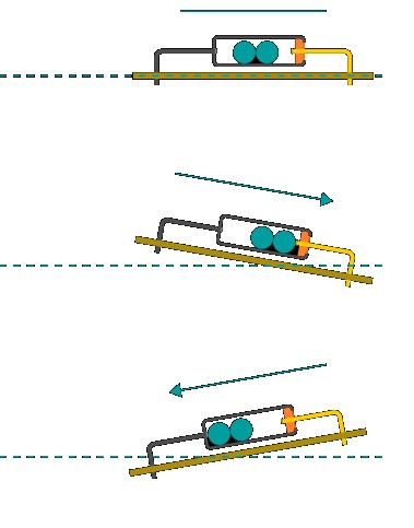
The SW-420 operates as a single-roller induction trigger switch. When at rest or upright, the internal conductive balls maintain a closed circuit. On tilting or vibrating the sensor, the internal contacts are disrupted, generating a brief pulse or breaking the circuit. This signal is used as a digital input trigger in electronic systems.
It reacts when tilted more than 15° from horizontal. If tilted toward terminal A, the circuit opens (OFF); if tilted toward terminal C, it closes (ON).

Pinout of SW-420 Module:

- VCC: Power supply (3.3V–5V)
- GND: Ground
- DO: Digital Output
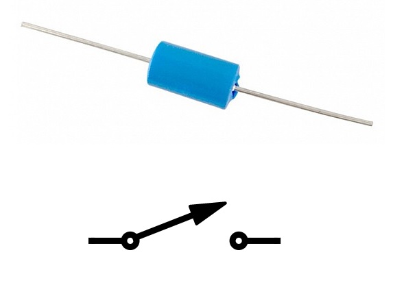
You may use the sensor's two legs as a basic switch without polarity sensitivity.
Applications:
- Theft Alarm Systems
- Earthquake Alarms
- Motorcycle or Vehicle Vibration Detectors
- Smart Toys and Gadgets
Circuit Example with Arduino UNO:
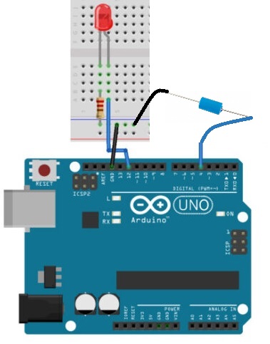
Connect the tilt sensor to digital pin 4 and an LED to digital pin 12 through a 220Ω resistor. Upload the following code and observe how the LED reacts to tilting or vibrating the sensor.

Code Example:
int ledPin = 12;
int sensorPin = 4;
int sensorValue;
int lastTiltState = HIGH;

long lastDebounceTime = 0;
long debounceDelay = 50;

void setup(){
  pinMode(sensorPin, INPUT);
  digitalWrite(sensorPin, HIGH);
  pinMode(ledPin, OUTPUT);
  Serial.begin(9600);
}

void loop(){
  sensorValue = digitalRead(sensorPin);

  if (sensorValue == lastTiltState) {
    lastDebounceTime = millis();
  }

  if ((millis() - lastDebounceTime) > debounceDelay) {
    lastTiltState = sensorValue;
  }

  digitalWrite(ledPin, lastTiltState);
  Serial.println(sensorValue);
  delay(500);
}
Technical Specifications:
- Voltage: < 12V
- Current: < 20mA
- Conductive Time: Approx. 1s
- Closed Resistance: 0–200Ω
- Open Resistance: >10MΩ
- Temperature Range: -40°C to 80°C
- Humidity: 95% RH @ 40°C for 96h
- Terminal Pull Strength: 500gf for 1 min
- Operating Lifespan: Over 1,000,000 cycles
Comparison with Other Tilt Sensors:
- Ball-in-Cage Switches: Use a solid metal ball for contact. Less affected by vibration due to heavier construction.
- Mercury Tilt Switches: Use mercury to make contact. High vibration resistance but are now discouraged due to mercury's toxicity.
Features:
- Operating Voltage: 3.3V – 5V
- Low current consumption (typically 25mA)
- Easy to interface with microcontrollers like Arduino
- Compact, reliable, and cost-effective
- Durable and waterproof sealed design
Principle of Operation:
The SW-420 operates as a single-roller induction trigger switch. When at rest or upright, the internal conductive balls maintain a closed circuit. On tilting or vibrating the sensor, the internal contacts are disrupted, generating a brief pulse or breaking the circuit. This signal is used as a digital input trigger in electronic systems.
It reacts when tilted more than 15° from horizontal. If tilted toward terminal A, the circuit opens (OFF); if tilted toward terminal C, it closes (ON).

Pinout of SW-420 Module:

- VCC: Power supply (3.3V–5V)
- GND: Ground
- DO: Digital Output
You may use the sensor's two legs as a basic switch without polarity sensitivity.
Applications:
- Theft Alarm Systems
- Earthquake Alarms
- Motorcycle or Vehicle Vibration Detectors
- Smart Toys and Gadgets
Circuit Example with Arduino UNO:
Connect the tilt sensor to digital pin 4 and an LED to digital pin 12 through a 220Ω resistor. Upload the following code and observe how the LED reacts to tilting or vibrating the sensor.

Code Example:
int ledPin = 12;
int sensorPin = 4;
int sensorValue;
int lastTiltState = HIGH;

long lastDebounceTime = 0;
long debounceDelay = 50;

void setup(){
  pinMode(sensorPin, INPUT);
  digitalWrite(sensorPin, HIGH);
  pinMode(ledPin, OUTPUT);
  Serial.begin(9600);
}

void loop(){
  sensorValue = digitalRead(sensorPin);

  if (sensorValue == lastTiltState) {
    lastDebounceTime = millis();
  }

  if ((millis() - lastDebounceTime) > debounceDelay) {
    lastTiltState = sensorValue;
  }

  digitalWrite(ledPin, lastTiltState);
  Serial.println(sensorValue);
  delay(500);
}
Technical Specifications:
- Voltage: < 12V
- Current: < 20mA
- Conductive Time: Approx. 1s
- Closed Resistance: 0–200Ω
- Open Resistance: >10MΩ
- Temperature Range: -40°C to 80°C
- Humidity: 95% RH @ 40°C for 96h
- Terminal Pull Strength: 500gf for 1 min
- Operating Lifespan: Over 1,000,000 cycles
Comparison with Other Tilt Sensors:
- Ball-in-Cage Switches: Use a solid metal ball for contact. Less affected by vibration due to heavier construction.
- Mercury Tilt Switches: Use mercury to make contact. High vibration resistance but are now discouraged due to mercury's toxicity.


