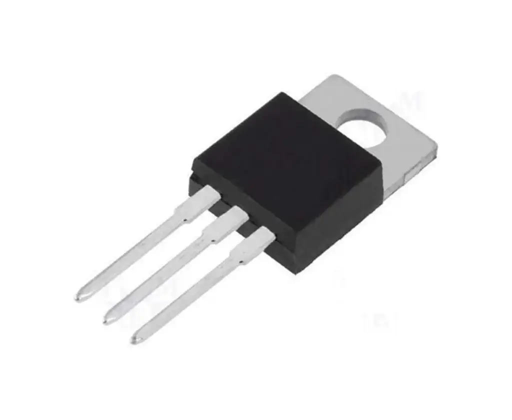
DC-DC LM338T Adjustable Voltage Regulator
Features:
- Adjustable output voltage: 1.2V to 37V
- Output current: 5A continuous (up to 7A peak with heatsink)
- High line regulation: typically 0.005%/V
- Thermal shutdown and current limiting protection
- Low thermal drift and excellent load regulation
- TO-220 and TO-3 packages available
Pinout:
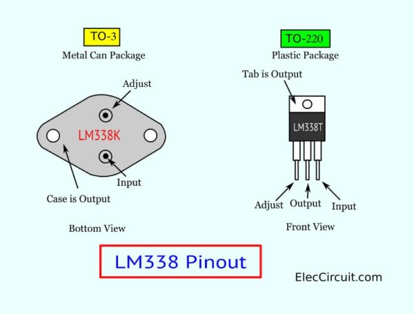
Pin Configuration:
- Pin 1: Adjust
- Pin 2: Output
- Pin 3: Input
Basic Voltage Setting Formula:
The output voltage is set using two resistors (R1 and R2):
Vout = 1.25V × (1 + R2 / R1)
(Iadj is very small and often ignored in calculations)
Example:
- R1 = 270Ω, R2 = 390Ω
- Vout = 3.06V
Example Resistor Values:
Here are some common resistor pairs for setting specific output voltages:
- 1.43V → R1 = 470Ω, R2 = 68Ω
- 2.50V → R1 = 470Ω, R2 = 470Ω
- 5.05V → R1 = 270Ω, R2 = 820Ω
- 10.00V → R1 = 220Ω, R2 = 3.3K
- 20.00V → R1 = 220Ω, R2 = 3.3K
- 28.75V → R1 = 150Ω, R2 = 3.3K
(Use standard resistor values available locally for convenience.)
1.2V to 30V / 5A Adjustable Power Supply Circuit
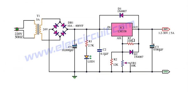
Working Principle:
This circuit uses a 24V transformer to deliver AC voltage, which is rectified by a bridge rectifier (BD1) and filtered by capacitor C1. The LM338 regulates the output voltage based on the value set by the variable resistor VR1 and resistor R1. Capacitor C3 smoothens the final output voltage.
Parts List:
- IC1: LM338K / LM338T
- D1: Bridge Diode 10A
- D2, D3: 1N4007 Diodes
- R1: 220Ω, 0.5W
- R2: 12KΩ, 0.5W
- VR1: 10KΩ Potentiometer
- C1, C3: 4700µF, 50V Electrolytic Capacitors
- C2: 0.1µF, 50V Ceramic Capacitor
- LED: 5mm Indicator
- T1: 24V 5A Transformer
PCB Layout:
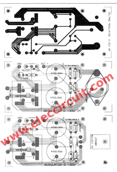
Note: Use a large heatsink for the LM338 to ensure thermal protection under high current loads. Pay special attention to the polarity of electrolytic capacitors during assembly.
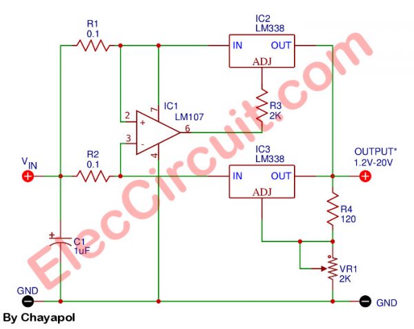
1.2V to 20V / 10A Adjustable Power Supply Circuit
Overview:
To achieve higher output current (up to 10A), this circuit uses two LM338 regulators in parallel. The output voltage is adjustable from 1.2V to 20V using VR1. This setup provides higher current capacity for heavier loads while maintaining voltage regulation and thermal protection.
Protection:
- Redundancy via parallel regulators
- Current limiting per device
- Improved load sharing
Summary:
- LM338 is a cost-effective, robust voltage regulator
- Simple design using few components
- Scalable output current via parallel configuration
- Adjustable voltage output makes it suitable for a wide range of DC-powered projects
Resources:
Features:
- Adjustable output voltage: 1.2V to 37V
- Output current: 5A continuous (up to 7A peak with heatsink)
- High line regulation: typically 0.005%/V
- Thermal shutdown and current limiting protection
- Low thermal drift and excellent load regulation
- TO-220 and TO-3 packages available
Pinout:
Pin Configuration:
- Pin 1: Adjust
- Pin 2: Output
- Pin 3: Input
Basic Voltage Setting Formula:
The output voltage is set using two resistors (R1 and R2):
Vout = 1.25V × (1 + R2 / R1)
(Iadj is very small and often ignored in calculations)
Example:
- R1 = 270Ω, R2 = 390Ω
- Vout = 3.06V
Example Resistor Values:
Here are some common resistor pairs for setting specific output voltages:
- 1.43V → R1 = 470Ω, R2 = 68Ω
- 2.50V → R1 = 470Ω, R2 = 470Ω
- 5.05V → R1 = 270Ω, R2 = 820Ω
- 10.00V → R1 = 220Ω, R2 = 3.3K
- 20.00V → R1 = 220Ω, R2 = 3.3K
- 28.75V → R1 = 150Ω, R2 = 3.3K
(Use standard resistor values available locally for convenience.)
1.2V to 30V / 5A Adjustable Power Supply Circuit
Working Principle:
This circuit uses a 24V transformer to deliver AC voltage, which is rectified by a bridge rectifier (BD1) and filtered by capacitor C1. The LM338 regulates the output voltage based on the value set by the variable resistor VR1 and resistor R1. Capacitor C3 smoothens the final output voltage.
Parts List:
- IC1: LM338K / LM338T
- D1: Bridge Diode 10A
- D2, D3: 1N4007 Diodes
- R1: 220Ω, 0.5W
- R2: 12KΩ, 0.5W
- VR1: 10KΩ Potentiometer
- C1, C3: 4700µF, 50V Electrolytic Capacitors
- C2: 0.1µF, 50V Ceramic Capacitor
- LED: 5mm Indicator
- T1: 24V 5A Transformer
PCB Layout:
Note: Use a large heatsink for the LM338 to ensure thermal protection under high current loads. Pay special attention to the polarity of electrolytic capacitors during assembly.
1.2V to 20V / 10A Adjustable Power Supply Circuit
Overview:
To achieve higher output current (up to 10A), this circuit uses two LM338 regulators in parallel. The output voltage is adjustable from 1.2V to 20V using VR1. This setup provides higher current capacity for heavier loads while maintaining voltage regulation and thermal protection.
Protection:
- Redundancy via parallel regulators
- Current limiting per device
- Improved load sharing
Summary:
- LM338 is a cost-effective, robust voltage regulator
- Simple design using few components
- Scalable output current via parallel configuration
- Adjustable voltage output makes it suitable for a wide range of DC-powered projects