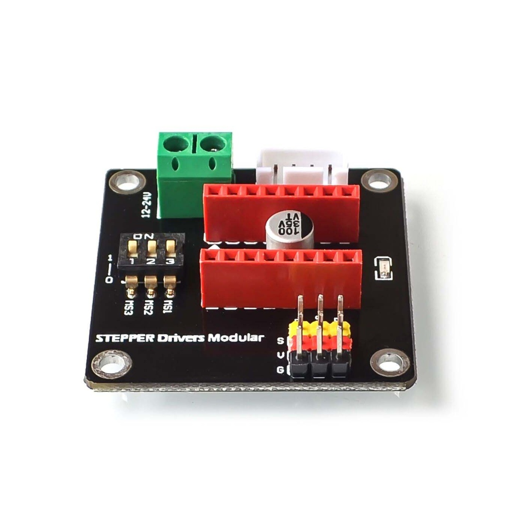
Stepper Motor Driver DRV8825 A4988 42 Expansion Board
The Stepper Motor Driver DRV8825 A4988 42 Expansion Board is a small-sized module that allows easy adjustment of the drive segments using the onboard DIP switch. It comes with digital ports and is compatible with both A4988 and DRV8825 drivers.
Package Includes:
- 1 x Stepper Motor Driver DRV8825 A4988 42 Expansion Board
Features:
- On-board DIP switch for easy adjustment of drive segments
- Digital ports compatible with A4988 and DRV8825 drivers
- Terminal power connectors for easy connection of drive power
- Compatible with 12/24V drive scheme
- The logic voltage of 5V and input voltage ranging from 12-30V
- Suitable for 42 stepper motor drives, 3D printers, and DIY projects
- Interfaces for rotation enable, direction, and speed control are all led out
- Compatible with the Arduino 3P interface
- Compact size of 42 x 42 x 15mm
- Uses A4988 and DRV8825 chips on the board
Principle of Work:
The board interfaces a microcontroller with a stepper motor, using a DIP switch to control step modes. The input signals manage direction, enable, and step control. It supports external motor power while sharing GND with the microcontroller.
Pinout of the Module:
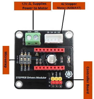
- VIN: Motor power input (12–24V)
- GND: Ground reference
- VDD: Logic power input (3V–5V)
- DIR: Direction control (HIGH/LOW)
- STP: Step control input (pulse-based)
- MS1, MS2, MS3: Microstepping mode selection
- EN: Enable signal
- MA, MB: Stepper motor coil outputs
Applications:
- Robotics: For precise control of robotic arms or mechanisms
- CNC Machines: Controls motors in 3D printers, laser cutters, mills
- Automation: Used for conveyor systems and robotic automation
- Camera Sliders: Time-lapse and video slider control
- Telescope Mounts: Accurate celestial tracking
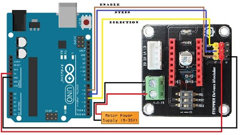
Circuit:
The stepper motor driver board connects to Arduino using pin 6 (enable), pin 5 (step), and pin 4 (direction). Power must be supplied externally, while GND is shared with Arduino.
Library:
No library needed
Code:
int Index;

void setup()
{
  pinMode(6, OUTPUT); // Enable
  pinMode(5, OUTPUT); // Step
  pinMode(4, OUTPUT); // Direction
  digitalWrite(6, LOW);
}

void loop()
{
  digitalWrite(4, HIGH);
  for (Index = 0; Index < 2000; Index++)
  {
    digitalWrite(5, HIGH);
    delayMicroseconds(500);
    digitalWrite(5, LOW);
    delayMicroseconds(500);
  }

  delay(1000);
  digitalWrite(4, LOW);

  for (Index = 0; Index < 2000; Index++)
  {
    digitalWrite(5, HIGH);
    delayMicroseconds(500);
    digitalWrite(5, LOW);
    delayMicroseconds(500);
  }

  delay(1000);
}
Explanation:
The loop alternates stepper motor direction by setting the DIR pin HIGH or LOW, then sends 2000 step pulses with delays for rotation. After a short pause, the direction changes and repeats.
Technical Details:
- Size: 42 x 42 x 15mm
- Mounting Hole: 3mm
- Pitch: 1400 x 1400mil (35.56 x 35.56mm)
- Logic Voltage: 5V
- Input Voltage: 12–24V
- Ports: Digital
- Interface: Direction, Enable, Speed
- Compatible Drivers: A4988, DRV8825
Comparisons:
Without this expansion board, users must directly connect DRV8825/A4988 modules to the microcontroller and manage all wiring manually. With the expansion board, stepper control is easier, faster, and more beginner-friendly with onboard circuitry and pin breakout for direct plug-and-play use.
Features:
- On-board DIP switch for easy adjustment of drive segments
- Digital ports compatible with A4988 and DRV8825 drivers
- Terminal power connectors for easy connection of drive power
- Compatible with 12/24V drive scheme
- The logic voltage of 5V and input voltage ranging from 12-30V
- Suitable for 42 stepper motor drives, 3D printers, and DIY projects
- Interfaces for rotation enable, direction, and speed control are all led out
- Compatible with the Arduino 3P interface
- Compact size of 42 x 42 x 15mm
- Uses A4988 and DRV8825 chips on the board
Principle of Work:
The board interfaces a microcontroller with a stepper motor, using a DIP switch to control step modes. The input signals manage direction, enable, and step control. It supports external motor power while sharing GND with the microcontroller.
Pinout of the Module:
- VIN: Motor power input (12–24V)
- GND: Ground reference
- VDD: Logic power input (3V–5V)
- DIR: Direction control (HIGH/LOW)
- STP: Step control input (pulse-based)
- MS1, MS2, MS3: Microstepping mode selection
- EN: Enable signal
- MA, MB: Stepper motor coil outputs
Applications:
- Robotics: For precise control of robotic arms or mechanisms
- CNC Machines: Controls motors in 3D printers, laser cutters, mills
- Automation: Used for conveyor systems and robotic automation
- Camera Sliders: Time-lapse and video slider control
- Telescope Mounts: Accurate celestial tracking
Circuit:
The stepper motor driver board connects to Arduino using pin 6 (enable), pin 5 (step), and pin 4 (direction). Power must be supplied externally, while GND is shared with Arduino.
Library:
No library needed
Code:
int Index;

void setup()
{
  pinMode(6, OUTPUT); // Enable
  pinMode(5, OUTPUT); // Step
  pinMode(4, OUTPUT); // Direction
  digitalWrite(6, LOW);
}

void loop()
{
  digitalWrite(4, HIGH);
  for (Index = 0; Index < 2000; Index++)
  {
    digitalWrite(5, HIGH);
    delayMicroseconds(500);
    digitalWrite(5, LOW);
    delayMicroseconds(500);
  }

  delay(1000);
  digitalWrite(4, LOW);

  for (Index = 0; Index < 2000; Index++)
  {
    digitalWrite(5, HIGH);
    delayMicroseconds(500);
    digitalWrite(5, LOW);
    delayMicroseconds(500);
  }

  delay(1000);
}
Explanation:
The loop alternates stepper motor direction by setting the DIR pin HIGH or LOW, then sends 2000 step pulses with delays for rotation. After a short pause, the direction changes and repeats.
Technical Details:
- Size: 42 x 42 x 15mm
- Mounting Hole: 3mm
- Pitch: 1400 x 1400mil (35.56 x 35.56mm)
- Logic Voltage: 5V
- Input Voltage: 12–24V
- Ports: Digital
- Interface: Direction, Enable, Speed
- Compatible Drivers: A4988, DRV8825
Comparisons:
Without this expansion board, users must directly connect DRV8825/A4988 modules to the microcontroller and manage all wiring manually. With the expansion board, stepper control is easier, faster, and more beginner-friendly with onboard circuitry and pin breakout for direct plug-and-play use.