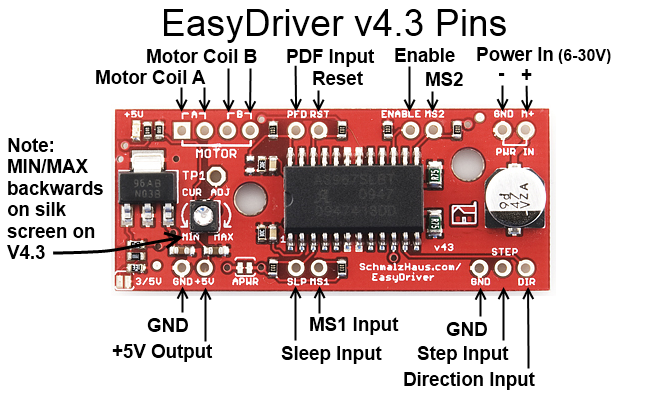
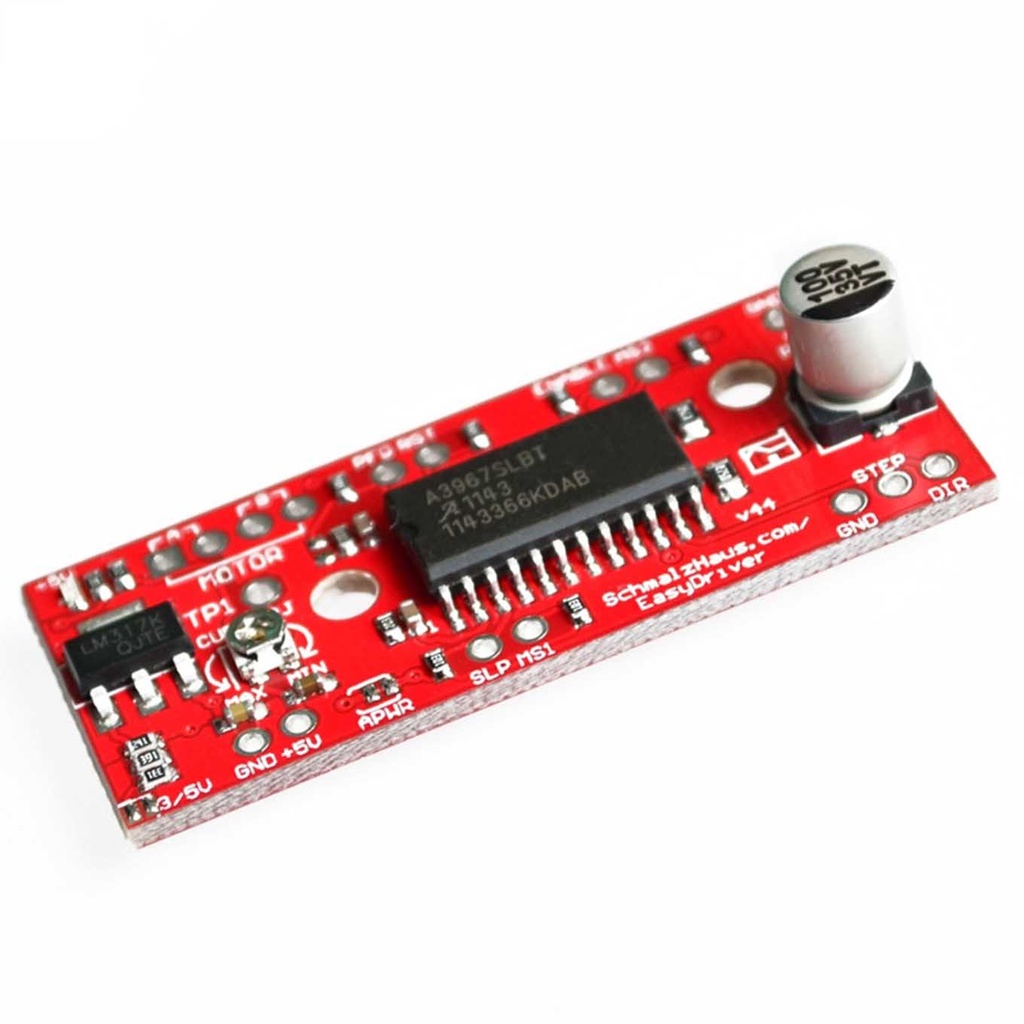
Stepper Motor Driver A3967 EasyDriver Pinout Description:
- GND: Three ground pins connected internally.
- M+: Power input (6V to 30V, 2A+ clean supply).
- A and B: Four motor connection pins for two coils.
- STEP: Digital signal (0–5V or 0–3.3V) for stepping.
- DIR: Direction signal; determines step direction.
- MS1/MS2: Microstepping mode control:
- 0,0 = Full step
- 1,0 = Half step
- 0,1 = Quarter step
- 1,1 = 1/8 step (default)
- RST: Reset pin (active low).
- SLP: Sleep pin (active low).
- ENABLE: Output disable when pulled high.
- +5V: Regulated 5V output (not input), limited to ~50mA.
- 3/5V JUMPER: Selects 3.3V or 5V logic level for control signals.APWR: Disconnects internal logic supply to use external 5V/3.3V Vcc.

Stepper Motor Driver A3967 EasyDriver Step Resolution Table:
| MS1 |
MS2 |
Resolution |
| low |
low |
Full Step (2 phase) |
| high |
low |
Half Step |
| low |
high |
Quarter Step |
| high |
high |
Eight Step |
Code for Stepper Motor Driver A3967 EasyDriver with Arduino:
First, you need to download and add the AccelStepper library to the Arduino IDE.
#include <AccelStepper.h>

// Define the stepper and the pins it will use
AccelStepper stepper1(AccelStepper::DRIVER, 9, 8);

// Define our three input button pins
#define LEFT_PIN 4
#define STOP_PIN 3
#define RIGHT_PIN 2

// Define our analog pot input pin
#define SPEED_PIN 0

// Define our maximum and minimum speed in steps per second (scale pot to these)
#define MAX_SPEED 500
#define MIN_SPEED 0.1

void setup() {
  stepper1.setMaxSpeed(10000.0); // Set max speed higher than needed
  pinMode(LEFT_PIN, INPUT_PULLUP);
  pinMode(STOP_PIN, INPUT_PULLUP);
  pinMode(RIGHT_PIN, INPUT_PULLUP);
}

void loop() {
  static float current_speed = 0.0;
  static int analog_read_counter = 1000;
  static char sign = 0;
  static int analog_value = 0;

  if (digitalRead(LEFT_PIN) == 0) {
    sign = 1;
  } else if (digitalRead(RIGHT_PIN) == 0) {
    sign = -1;
  } else if (digitalRead(STOP_PIN) == 0) {
    sign = 0;
  }

  if (analog_read_counter > 0) {
    analog_read_counter--;
  } else {
    analog_read_counter = 3000;
    analog_value = analogRead(SPEED_PIN);
    stepper1.runSpeed();
    current_speed = sign * (((analog_value / 1023.0) * (MAX_SPEED - MIN_SPEED)) + MIN_SPEED);
    stepper1.setSpeed(current_speed);
  }

  stepper1.runSpeed();
}
Code Explanation:
The code uses `runSpeed()` instead of `run()` because it runs the stepper motor at a constant speed. Analog value reading and mathematical operations are spaced out to reduce delays. You can adjust `MIN_SPEED` and `MAX_SPEED` as needed.
Stepper Motor Driver A3967 EasyDriver Pinout Description:
- GND: Three ground pins connected internally.
- M+: Power input (6V to 30V, 2A+ clean supply).
- A and B: Four motor connection pins for two coils.
- STEP: Digital signal (0–5V or 0–3.3V) for stepping.
- DIR: Direction signal; determines step direction.
- MS1/MS2: Microstepping mode control:
- 0,0 = Full step
- 1,0 = Half step
- 0,1 = Quarter step
- 1,1 = 1/8 step (default)
- RST: Reset pin (active low).
- SLP: Sleep pin (active low).
- ENABLE: Output disable when pulled high.
- +5V: Regulated 5V output (not input), limited to ~50mA.
- 3/5V JUMPER: Selects 3.3V or 5V logic level for control signals.APWR: Disconnects internal logic supply to use external 5V/3.3V Vcc.

Stepper Motor Driver A3967 EasyDriver Step Resolution Table:
| MS1 |
MS2 |
Resolution |
| low |
low |
Full Step (2 phase) |
| high |
low |
Half Step |
| low |
high |
Quarter Step |
| high |
high |
Eight Step |
Code for Stepper Motor Driver A3967 EasyDriver with Arduino:
First, you need to download and add the AccelStepper library to the Arduino IDE.
#include <AccelStepper.h>

// Define the stepper and the pins it will use
AccelStepper stepper1(AccelStepper::DRIVER, 9, 8);

// Define our three input button pins
#define LEFT_PIN 4
#define STOP_PIN 3
#define RIGHT_PIN 2

// Define our analog pot input pin
#define SPEED_PIN 0

// Define our maximum and minimum speed in steps per second (scale pot to these)
#define MAX_SPEED 500
#define MIN_SPEED 0.1

void setup() {
  stepper1.setMaxSpeed(10000.0); // Set max speed higher than needed
  pinMode(LEFT_PIN, INPUT_PULLUP);
  pinMode(STOP_PIN, INPUT_PULLUP);
  pinMode(RIGHT_PIN, INPUT_PULLUP);
}

void loop() {
  static float current_speed = 0.0;
  static int analog_read_counter = 1000;
  static char sign = 0;
  static int analog_value = 0;

  if (digitalRead(LEFT_PIN) == 0) {
    sign = 1;
  } else if (digitalRead(RIGHT_PIN) == 0) {
    sign = -1;
  } else if (digitalRead(STOP_PIN) == 0) {
    sign = 0;
  }

  if (analog_read_counter > 0) {
    analog_read_counter--;
  } else {
    analog_read_counter = 3000;
    analog_value = analogRead(SPEED_PIN);
    stepper1.runSpeed();
    current_speed = sign * (((analog_value / 1023.0) * (MAX_SPEED - MIN_SPEED)) + MIN_SPEED);
    stepper1.setSpeed(current_speed);
  }

  stepper1.runSpeed();
}
Code Explanation:
The code uses `runSpeed()` instead of `run()` because it runs the stepper motor at a constant speed. Analog value reading and mathematical operations are spaced out to reduce delays. You can adjust `MIN_SPEED` and `MAX_SPEED` as needed.

