
Robot 4WD Smart Robot Car Double Layers Kit Green
The 4WD Smart Robot Car chassis kit is an excellent project for robotics and DIY electronics enthusiasts. It includes all the necessary parts to build a fully functional robot car.
Package Includes:
- 4 Tires
- 6 Fasteners
- 2 Smart Car Chassis
- 4 DC Gear Motors
- 4 Encoders
- 1 Set of Screws, Nuts, and Copper Pillars
Assembly Instructions:
- Start by assembling the chassis: join the two smart car chassis pieces using the screws and nuts.
- Attach the four DC gear motors to the bottom of the chassis using screws and nuts.
- Secure the four encoders to the DC gear motors with the provided screws and nuts.
- Fix the four tires onto the shafts of the respective gear motors.
- Connect the wires from each motor to a motor driver board or microcontroller, following your specific hardware instructions.
- Power the robot with a battery or power supply and test movement by sending commands to the motor driver or microcontroller.
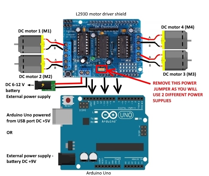
Circuit Connection:
Below is the connection guide for the L293D 4 motor shield with Arduino:
| L293D Motor Shield | Arduino Uno |
|---|---|
| VCC | 5V |
| GND | GND |
| IN1 | Digital Pin 2 (D2) |
| IN2 | Digital Pin 3 (D3) |
| IN3 | Digital Pin 4 (D4) |
| IN4 | Digital Pin 5 (D5) |
Connect motors to the motor shield's M1, M2, M3, and M4 ports. Each motor has two wires: the positive connects to terminal A and the negative to terminal B on the shield.
Library Installation for L293D Motor Shield:
- Download the Adafruit Motor Shield library from GitHub.
- Extract the downloaded ZIP file to a folder on your computer.
- Open the Arduino IDE.
- Go to Sketch > Include Library > Add .ZIP Library.
- Select the extracted ZIP file
Adafruit_Motor_Shield_library-master.zipand click Open. - The library will be installed, and a success message will appear in the IDE.
Example Arduino Code to Control 4WD Robot Using L293D Shield
// Include the AFMotor library
#include <AFMotor.h>

// Create motor objects for the four motors
AF_DCMotor motor1(1, MOTOR12_64KHZ);
AF_DCMotor motor2(2, MOTOR12_64KHZ);
AF_DCMotor motor3(3, MOTOR34_64KHZ);
AF_DCMotor motor4(4, MOTOR34_64KHZ);

void setup() {
  Serial.begin(9600);
  AFMS.begin(); // Initialize motor shield, default freq 1.6KHz

  motor1.setSpeed(200);
  motor2.setSpeed(200);
  motor3.setSpeed(200);
  motor4.setSpeed(200);
}

void loop() {
  moveForward();
  delay(1000);

  stopRobot();
  delay(500);

  turnLeft();
  delay(1000);

  stopRobot();
  delay(500);

  turnRight();
  delay(1000);

  stopRobot();
  delay(500);

  moveBackward();
  delay(1000);

  stopRobot();
  delay(500);
}

void moveForward() {
  motor1.run(FORWARD);
  motor2.run(FORWARD);
  motor3.run(FORWARD);
  motor4.run(FORWARD);
}

void moveBackward() {
  motor1.run(BACKWARD);
  motor2.run(BACKWARD);
  motor3.run(BACKWARD);
  motor4.run(BACKWARD);
}

void turnLeft() {
  motor1.run(FORWARD);
  motor2.run(FORWARD);
  motor3.run(BACKWARD);
  motor4.run(BACKWARD);
}

void turnRight() {
  motor1.run(BACKWARD);
  motor2.run(BACKWARD);
  motor3.run(FORWARD);
  motor4.run(FORWARD);
}

void stopRobot() {
  motor1.run(RELEASE);
  motor2.run(RELEASE);
  motor3.run(RELEASE);
  motor4.run(RELEASE);
}
Specifications:
- Working Voltage: DC 3V / 5V / 6V
- Working Current: 100mA / 100mA / 120mA
- No-load Speed (with wheel): 100 RPM / 190 RPM / 240 RPM
- Speed (no-load): 20 m/min, 39 m/min, 48 m/min
- Noise: < 65 dB
- Wheel Diameter: 66 mm (approx.)
- Dimensions (L × W × H): 25.5 × 15.5 × 6.5 cm (approx.)
Note: The robot's performance depends on the motor driver or microcontroller used, power source, and programming.
Assembly Instructions:
- Start by assembling the chassis: join the two smart car chassis pieces using the screws and nuts.
- Attach the four DC gear motors to the bottom of the chassis using screws and nuts.
- Secure the four encoders to the DC gear motors with the provided screws and nuts.
- Fix the four tires onto the shafts of the respective gear motors.
- Connect the wires from each motor to a motor driver board or microcontroller, following your specific hardware instructions.
- Power the robot with a battery or power supply and test movement by sending commands to the motor driver or microcontroller.
Circuit Connection:
Below is the connection guide for the L293D 4 motor shield with Arduino:
| L293D Motor Shield | Arduino Uno |
|---|---|
| VCC | 5V |
| GND | GND |
| IN1 | Digital Pin 2 (D2) |
| IN2 | Digital Pin 3 (D3) |
| IN3 | Digital Pin 4 (D4) |
| IN4 | Digital Pin 5 (D5) |
Connect motors to the motor shield's M1, M2, M3, and M4 ports. Each motor has two wires: the positive connects to terminal A and the negative to terminal B on the shield.
Library Installation for L293D Motor Shield:
- Download the Adafruit Motor Shield library from GitHub.
- Extract the downloaded ZIP file to a folder on your computer.
- Open the Arduino IDE.
- Go to Sketch > Include Library > Add .ZIP Library.
- Select the extracted ZIP file
Adafruit_Motor_Shield_library-master.zipand click Open. - The library will be installed, and a success message will appear in the IDE.
Example Arduino Code to Control 4WD Robot Using L293D Shield
// Include the AFMotor library
#include <AFMotor.h>

// Create motor objects for the four motors
AF_DCMotor motor1(1, MOTOR12_64KHZ);
AF_DCMotor motor2(2, MOTOR12_64KHZ);
AF_DCMotor motor3(3, MOTOR34_64KHZ);
AF_DCMotor motor4(4, MOTOR34_64KHZ);

void setup() {
  Serial.begin(9600);
  AFMS.begin(); // Initialize motor shield, default freq 1.6KHz

  motor1.setSpeed(200);
  motor2.setSpeed(200);
  motor3.setSpeed(200);
  motor4.setSpeed(200);
}

void loop() {
  moveForward();
  delay(1000);

  stopRobot();
  delay(500);

  turnLeft();
  delay(1000);

  stopRobot();
  delay(500);

  turnRight();
  delay(1000);

  stopRobot();
  delay(500);

  moveBackward();
  delay(1000);

  stopRobot();
  delay(500);
}

void moveForward() {
  motor1.run(FORWARD);
  motor2.run(FORWARD);
  motor3.run(FORWARD);
  motor4.run(FORWARD);
}

void moveBackward() {
  motor1.run(BACKWARD);
  motor2.run(BACKWARD);
  motor3.run(BACKWARD);
  motor4.run(BACKWARD);
}

void turnLeft() {
  motor1.run(FORWARD);
  motor2.run(FORWARD);
  motor3.run(BACKWARD);
  motor4.run(BACKWARD);
}

void turnRight() {
  motor1.run(BACKWARD);
  motor2.run(BACKWARD);
  motor3.run(FORWARD);
  motor4.run(FORWARD);
}

void stopRobot() {
  motor1.run(RELEASE);
  motor2.run(RELEASE);
  motor3.run(RELEASE);
  motor4.run(RELEASE);
}
Specifications:
- Working Voltage: DC 3V / 5V / 6V
- Working Current: 100mA / 100mA / 120mA
- No-load Speed (with wheel): 100 RPM / 190 RPM / 240 RPM
- Speed (no-load): 20 m/min, 39 m/min, 48 m/min
- Noise: < 65 dB
- Wheel Diameter: 66 mm (approx.)
- Dimensions (L × W × H): 25.5 × 15.5 × 6.5 cm (approx.)
Note: The robot's performance depends on the motor driver or microcontroller used, power source, and programming.