Features:
- Gear Ratio: 1:48
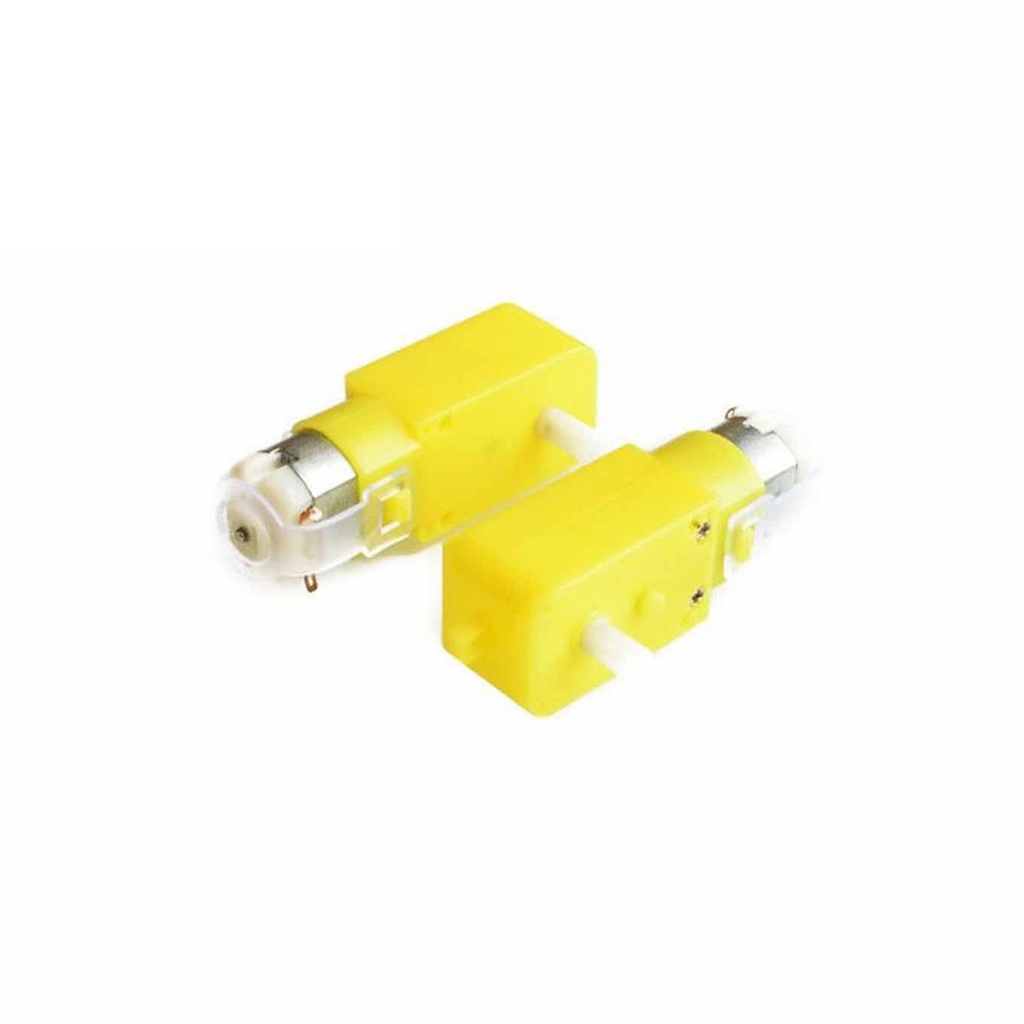
- Low cost and beginner-friendly
- Ideal for small robots and mechanical systems
- Breadboard and terminal block compatible
- Reversible rotation direction
Principle of Work:
When voltage is applied to the motor terminals, a magnetic field is generated inside the motor. This causes the rotor to spin, and through a gear train with a 1:48 ratio, the output shaft turns slowly but with increased torque. The gear reduction mechanism is what enables this motor to perform mechanical tasks efficiently with minimal input current.
Pinout:
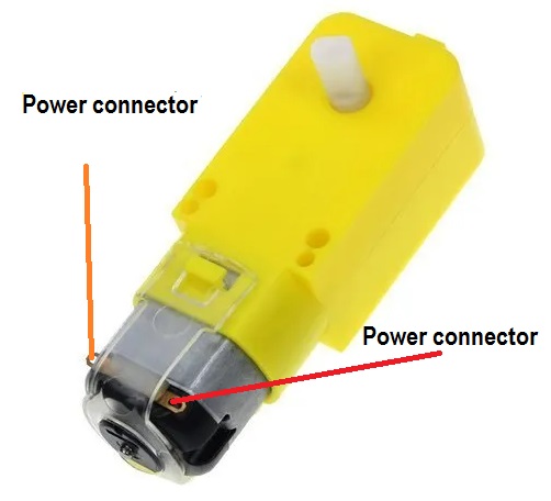
How to Connect:
- Red wire → +V (3–6V DC)
- Black wire → GND
Swap the connections to reverse motor direction.
Applications:
- Robotic cars and platforms
- Actuators for levers and doors
- Simple fans and mini pumps
- Educational robotic kits
Circuit Example:

Sample Arduino Code:
// Control motor speed with PWM using a transistor on pin 9
const int motorPin = 9;

void setup() {
  pinMode(motorPin, OUTPUT);
  Serial.begin(9600);
}

void loop() {
  serialSpeed(); // Control speed via Serial Monitor
}

void serialSpeed() {
  int speed;
  Serial.println("Type a speed (0-255) and press enter:");

  while (true) {
    if (Serial.available() > 0) {
      speed = Serial.parseInt();
      speed = constrain(speed, 0, 255);
      Serial.print("Setting speed to ");
      Serial.println(speed);
      analogWrite(motorPin, speed);
    }
  }
}
Hardware Notes:
- Use a 2N2222 transistor to switch the motor
- Use a flyback diode to prevent voltage spikes
- Connect transistor base via 330Ω resistor to Arduino pin
Technical Specifications:
| Working Voltage | DC 3–6V |
|---|---|
| Speed | 200 RPM |
| Gear Ratio | 1:48 |
| Gear Material | Plastic |
| Axis Type | Single Shaft |
| Rotation | Bidirectional |
| Operating Temperature | +10℃ to +50℃ |
| Storage Temperature | -10℃ to +40℃ |
Comparisons: Plastic vs Metal Gears
| Feature | Plastic Gear | Metal Gear |
|---|---|---|
| Durability | Less durable | More durable |
| Torque | Lower torque | Higher torque |
| Noise | Higher | Lower |
| Cost | Cheaper | More expensive |
Resources:
- No additional library is needed to control the motor.
- Ideal for learning PWM and basic motor control with Arduino.
Features:
- Gear Ratio: 1:48
- Low cost and beginner-friendly
- Ideal for small robots and mechanical systems
- Breadboard and terminal block compatible
- Reversible rotation direction
Principle of Work:
When voltage is applied to the motor terminals, a magnetic field is generated inside the motor. This causes the rotor to spin, and through a gear train with a 1:48 ratio, the output shaft turns slowly but with increased torque. The gear reduction mechanism is what enables this motor to perform mechanical tasks efficiently with minimal input current.
Pinout:
How to Connect:
- Red wire → +V (3–6V DC)
- Black wire → GND
Swap the connections to reverse motor direction.
Applications:
- Robotic cars and platforms
- Actuators for levers and doors
- Simple fans and mini pumps
- Educational robotic kits
Circuit Example:
Sample Arduino Code:
// Control motor speed with PWM using a transistor on pin 9
const int motorPin = 9;

void setup() {
  pinMode(motorPin, OUTPUT);
  Serial.begin(9600);
}

void loop() {
  serialSpeed(); // Control speed via Serial Monitor
}

void serialSpeed() {
  int speed;
  Serial.println("Type a speed (0-255) and press enter:");

  while (true) {
    if (Serial.available() > 0) {
      speed = Serial.parseInt();
      speed = constrain(speed, 0, 255);
      Serial.print("Setting speed to ");
      Serial.println(speed);
      analogWrite(motorPin, speed);
    }
  }
}
Hardware Notes:
- Use a 2N2222 transistor to switch the motor
- Use a flyback diode to prevent voltage spikes
- Connect transistor base via 330Ω resistor to Arduino pin
Technical Specifications:
| Working Voltage | DC 3–6V |
|---|---|
| Speed | 200 RPM |
| Gear Ratio | 1:48 |
| Gear Material | Plastic |
| Axis Type | Single Shaft |
| Rotation | Bidirectional |
| Operating Temperature | +10℃ to +50℃ |
| Storage Temperature | -10℃ to +40℃ |
Comparisons: Plastic vs Metal Gears
| Feature | Plastic Gear | Metal Gear |
|---|---|---|
| Durability | Less durable | More durable |
| Torque | Lower torque | Higher torque |
| Noise | Higher | Lower |
| Cost | Cheaper | More expensive |
Resources:
- No additional library is needed to control the motor.
- Ideal for learning PWM and basic motor control with Arduino.