Features:
- I2C Communication: Uses only two wires (SCL, SDA) to control up to 16 PWM outputs.
- 16 Independent Channels: Supports simultaneous control of up to 16 servo motors or LEDs.
- 12-Bit Resolution: Offers fine control with 4096 PWM steps for accurate positioning.
- Output Enable (OE): Provides a way to disable all outputs instantly via a dedicated pin.
- Dual Input Pins: Allows easy chaining of multiple modules.
- Standard PWM Ports: Each channel includes V+, GND, and PWM signal pins for organized wiring.
- Frequency Adjustable: PWM frequency can be changed to suit servos or LED dimming.
- Flexible Power Options: Supports external power for high-current servos (up to 6V).
- Arduino Compatible: Easily integrates with Uno, Nano, and other I2C-supported boards.
Specifications:
| Parameter | Value |
|---|---|
| Channels | 16 PWM Outputs |
| PWM Resolution | 12-Bit (4096 Steps) |
| PWM Frequency | Adjustable up to 1.6kHz |
| Operating Voltage | 3.3V - 5V Logic |
| Servo Voltage (V+) | Up to 6V (12V max with caution) |
| Current per Pin | 25mA (Max) |
| I2C Address Range | 0x40 to 0x7F (up to 62 modules) |
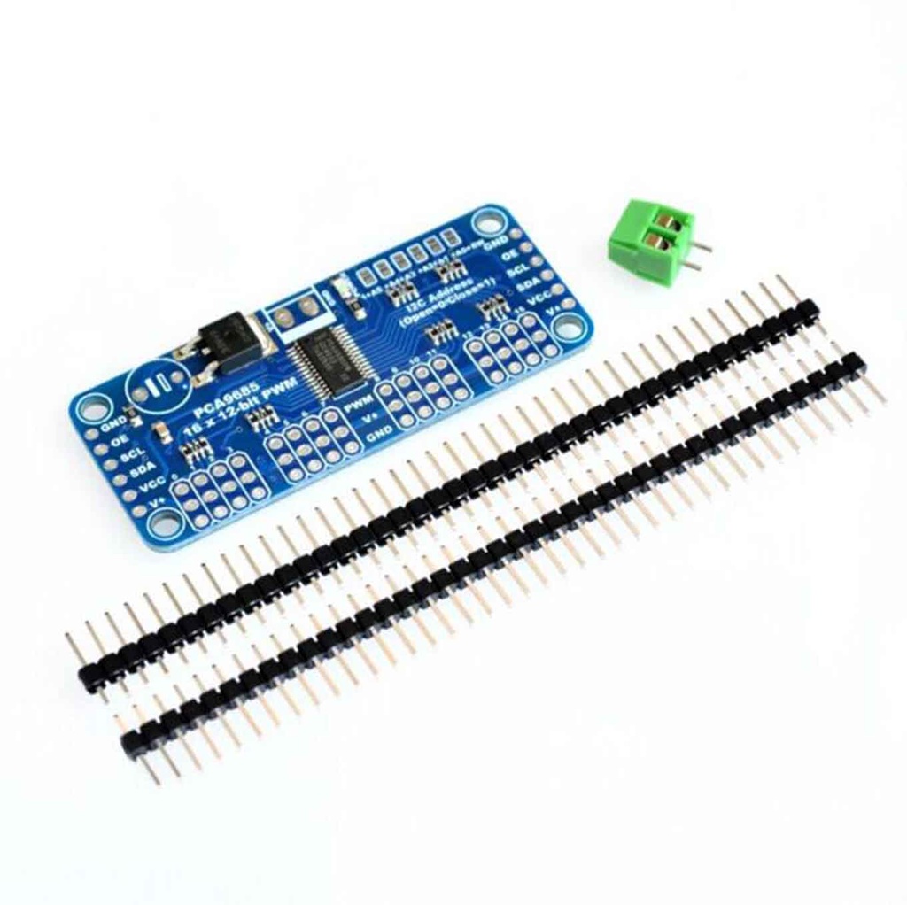
Pinout:

| Pin | Description |
|---|---|
| GND | Signal and power ground |
| VCC | Logic voltage input (3.3V–5V) |
| V+ | Power for servos (e.g., 5V–6V) |
| SCL | I2C clock line |
| SDA | I2C data line |
| OE | Output enable (Low = enabled) |
| PWM Outputs | 16x ports (each: V+, GND, PWM) |
I2C Addressing (A0–A5):
Each PCA9685 module has configurable address pins (A0 to A5) allowing up to 62 modules on a single I2C bus. Default address: 0x40.
- A0–A5: Pull high (default = 1), pull low = 0
- Example: A0 low, others high → Address =
0x41 - Example: A1 low, A0 low → Address =
0x43
Principle of Operation:
- Each of the 16 channels uses 12-bit PWM to control servo position or LED brightness.
- Uses the I2C bus for communication, allowing multiple modules on the same line.
- Each PWM signal is generated independently, but they all share the same frequency.
- Servo motors receive pulses between ~500µs (0°) and ~2500µs (180°).
Applications:
- Robotics: Control limbs or robotic arms with multiple servos.
- Animatronics: Smoothly animate faces, puppets, and creatures.
- Model Making: RC cars, planes, boats with extensive servo use.
- Automation: Open/close mechanisms in smart home systems.
- Educational: Great for students learning I2C, PWM, and servos.
- Lighting: Use PWM for dimming effects in LED projects.
Typical Circuit:
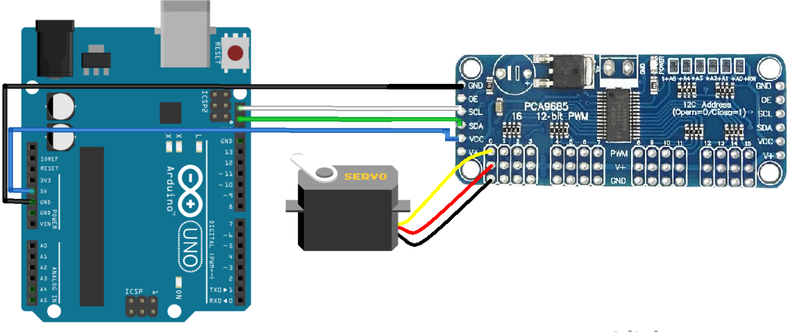
Library Installation:
- Open Arduino IDE
- Go to Sketch > Include Library > Manage Libraries…
- Search for Adafruit PWM Servo Driver
- Install the Adafruit_PWMServoDriver library
Sample Arduino Code:
#include "Wire.h"
#include "Adafruit_PWMServoDriver.h"

#define nbPCAServo 16

int MIN_IMP[nbPCAServo] = {500};
int MAX_IMP[nbPCAServo] = {2500};
int MIN_ANG[nbPCAServo] = {0};
int MAX_ANG[nbPCAServo] = {180};

Adafruit_PWMServoDriver pca = Adafruit_PWMServoDriver(0x40);

void setup() {
  Serial.begin(9600);
  Serial.println(F("Initialize System"));
  pca.begin();
  pca.setPWMFreq(60);  // 60 Hz for analog servos
}

void loop() {
  pcaScenario();  // Test movement
}

void pcaScenario() {
  for (int i = 0; i < nbPCAServo; i++) {
    Serial.print("Servo "); Serial.println(i);
    for (int pos = 1500; pos < MAX_IMP[i]; pos += 10) {
      pca.writeMicroseconds(i, pos);
      delay(10);
    }
    for (int pos = MAX_IMP[i]; pos > MIN_IMP[i]; pos -= 10) {
      pca.writeMicroseconds(i, pos);
      delay(10);
    }
    for (int pos = MIN_IMP[i]; pos < 1500; pos += 10) {
      pca.writeMicroseconds(i, pos);
      delay(10);
    }
    pca.setPin(i, 0, true); // Disable output
  }
}

int jointToImp(double x, int i) {
  int imp = (x - MIN_ANG[i]) * (MAX_IMP[i] - MIN_IMP[i]) / (MAX_ANG[i] - MIN_ANG[i]) + MIN_IMP[i];
  return constrain(imp, MIN_IMP[i], MAX_IMP[i]);
}
Comparison with L293D:
| Feature | PCA9685 | L293D |
|---|---|---|
| Function | Servo/LED PWM Driver | DC/Stepper Motor Driver |
| Channels | 16 PWM | 2 DC motors / 1 stepper |
| Communication | I2C | Direct GPIO |
| Expandability | Up to 62 modules (992 outputs) | Limited |
| PWM Resolution | 12-bit | Basic PWM |
| Best Use | Servo control & lighting | Driving motors |
Features:
- I2C Communication: Uses only two wires (SCL, SDA) to control up to 16 PWM outputs.
- 16 Independent Channels: Supports simultaneous control of up to 16 servo motors or LEDs.
- 12-Bit Resolution: Offers fine control with 4096 PWM steps for accurate positioning.
- Output Enable (OE): Provides a way to disable all outputs instantly via a dedicated pin.
- Dual Input Pins: Allows easy chaining of multiple modules.
- Standard PWM Ports: Each channel includes V+, GND, and PWM signal pins for organized wiring.
- Frequency Adjustable: PWM frequency can be changed to suit servos or LED dimming.
- Flexible Power Options: Supports external power for high-current servos (up to 6V).
- Arduino Compatible: Easily integrates with Uno, Nano, and other I2C-supported boards.
Specifications:
| Parameter | Value |
|---|---|
| Channels | 16 PWM Outputs |
| PWM Resolution | 12-Bit (4096 Steps) |
| PWM Frequency | Adjustable up to 1.6kHz |
| Operating Voltage | 3.3V - 5V Logic |
| Servo Voltage (V+) | Up to 6V (12V max with caution) |
| Current per Pin | 25mA (Max) |
| I2C Address Range | 0x40 to 0x7F (up to 62 modules) |
Pinout:
| Pin | Description |
|---|---|
| GND | Signal and power ground |
| VCC | Logic voltage input (3.3V–5V) |
| V+ | Power for servos (e.g., 5V–6V) |
| SCL | I2C clock line |
| SDA | I2C data line |
| OE | Output enable (Low = enabled) |
| PWM Outputs | 16x ports (each: V+, GND, PWM) |
I2C Addressing (A0–A5):
Each PCA9685 module has configurable address pins (A0 to A5) allowing up to 62 modules on a single I2C bus. Default address: 0x40.
- A0–A5: Pull high (default = 1), pull low = 0
- Example: A0 low, others high → Address =
0x41 - Example: A1 low, A0 low → Address =
0x43
Principle of Operation:
- Each of the 16 channels uses 12-bit PWM to control servo position or LED brightness.
- Uses the I2C bus for communication, allowing multiple modules on the same line.
- Each PWM signal is generated independently, but they all share the same frequency.
- Servo motors receive pulses between ~500µs (0°) and ~2500µs (180°).
Applications:
- Robotics: Control limbs or robotic arms with multiple servos.
- Animatronics: Smoothly animate faces, puppets, and creatures.
- Model Making: RC cars, planes, boats with extensive servo use.
- Automation: Open/close mechanisms in smart home systems.
- Educational: Great for students learning I2C, PWM, and servos.
- Lighting: Use PWM for dimming effects in LED projects.
Typical Circuit:
Library Installation:
- Open Arduino IDE
- Go to Sketch > Include Library > Manage Libraries…
- Search for Adafruit PWM Servo Driver
- Install the Adafruit_PWMServoDriver library
Sample Arduino Code:
#include "Wire.h"
#include "Adafruit_PWMServoDriver.h"

#define nbPCAServo 16

int MIN_IMP[nbPCAServo] = {500};
int MAX_IMP[nbPCAServo] = {2500};
int MIN_ANG[nbPCAServo] = {0};
int MAX_ANG[nbPCAServo] = {180};

Adafruit_PWMServoDriver pca = Adafruit_PWMServoDriver(0x40);

void setup() {
  Serial.begin(9600);
  Serial.println(F("Initialize System"));
  pca.begin();
  pca.setPWMFreq(60);  // 60 Hz for analog servos
}

void loop() {
  pcaScenario();  // Test movement
}

void pcaScenario() {
  for (int i = 0; i < nbPCAServo; i++) {
    Serial.print("Servo "); Serial.println(i);
    for (int pos = 1500; pos < MAX_IMP[i]; pos += 10) {
      pca.writeMicroseconds(i, pos);
      delay(10);
    }
    for (int pos = MAX_IMP[i]; pos > MIN_IMP[i]; pos -= 10) {
      pca.writeMicroseconds(i, pos);
      delay(10);
    }
    for (int pos = MIN_IMP[i]; pos < 1500; pos += 10) {
      pca.writeMicroseconds(i, pos);
      delay(10);
    }
    pca.setPin(i, 0, true); // Disable output
  }
}

int jointToImp(double x, int i) {
  int imp = (x - MIN_ANG[i]) * (MAX_IMP[i] - MIN_IMP[i]) / (MAX_ANG[i] - MIN_ANG[i]) + MIN_IMP[i];
  return constrain(imp, MIN_IMP[i], MAX_IMP[i]);
}
Comparison with L293D:
| Feature | PCA9685 | L293D |
|---|---|---|
| Function | Servo/LED PWM Driver | DC/Stepper Motor Driver |
| Channels | 16 PWM | 2 DC motors / 1 stepper |
| Communication | I2C | Direct GPIO |
| Expandability | Up to 62 modules (992 outputs) | Limited |
| PWM Resolution | 12-bit | Basic PWM |
| Best Use | Servo control & lighting | Driving motors |