Features:
- Dual Motor Control: Supports 2 DC motors or 1 stepper motor
- Wide Voltage Range: Operates between 5V and 35V
- Current Capacity: Up to 2A per channel
- Onboard 5V Regulator: Provides 5V output for external use
- PWM Speed Control: Enable pins for motor speed adjustments
- Built-in Heat Sink: Effective thermal dissipation
- Reverse Polarity Protection: Safe motor control
- Logic Level Support: Compatible with 3.3V and 5V systems
Specifications:
| Parameter | Value |
|---|---|
| Operating Voltage | 5V – 35V |
| Output Peak Current | 2A per channel |
| Logic Voltage | 4.5V – 5.5V |
| Logic Current | 0 – 36mA |
| PWM Control | Yes (Enable A & B) |
| Max Power | 20W |
| Operating Temperature | -25°C to 130°C |
| Module Size | 55 x 60 x 30 mm |
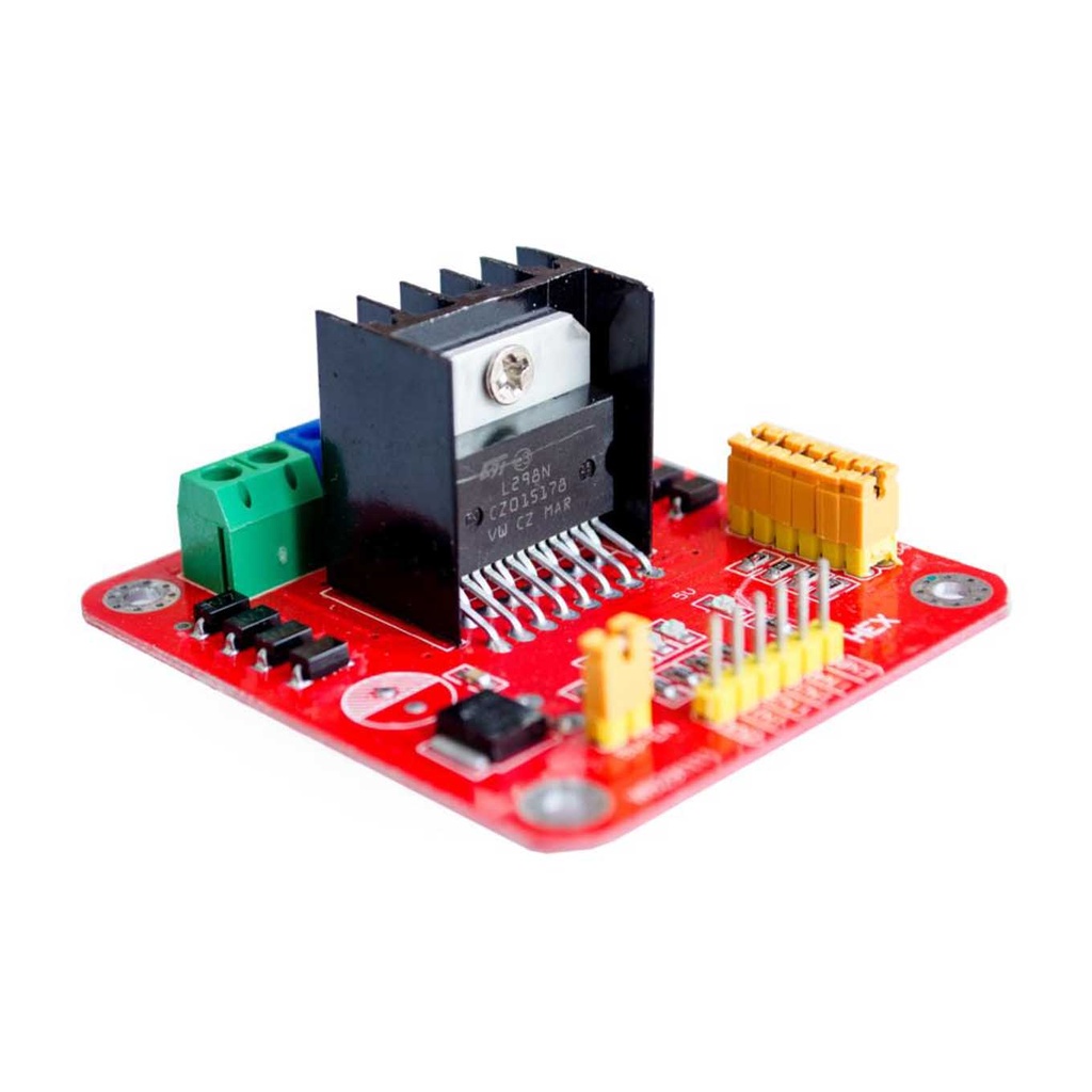
Pinout:
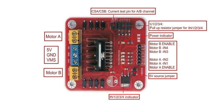
| Pin Label | Description |
|---|---|
| VMS | Motor Power Supply (5V–35V) |
| GND | Ground |
| 5V | 5V Output from onboard regulator |
| IN1, IN2 | Motor A control inputs |
| IN3, IN4 | Motor B control inputs |
| ENA, ENB | PWM speed control for Motor A & B |
| OUT1, OUT2 | Motor A outputs |
| OUT3, OUT4 | Motor B outputs |
Wiring Guide:
Example connections between L298N, Arduino, and a stepper motor:
| L298N Pin | Arduino Pin | Stepper Motor |
|---|---|---|
| ENA | 5V or PWM pin | - |
| IN1 | D8 | Coil 1A |
| IN2 | D9 | Coil 1B |
| IN3 | D10 | Coil 2A |
| IN4 | D11 | Coil 2B |
| ENB | 5V or PWM pin | - |
| VMS | 12V External | - |
| GND | GND | - |
Wiring Diagram:

Example Arduino Code:
// Define control pins
#define IN1 8
#define IN2 9
#define IN3 10
#define IN4 11
#define ENA 5
#define ENB 6

void setup() {
  pinMode(IN1, OUTPUT);
  pinMode(IN2, OUTPUT);
  pinMode(IN3, OUTPUT);
  pinMode(IN4, OUTPUT);
  pinMode(ENA, OUTPUT);
  pinMode(ENB, OUTPUT);

  digitalWrite(ENA, HIGH); // Enable Motor A
  digitalWrite(ENB, HIGH); // Enable Motor B
}

void loop() {
  // Rotate clockwise
  stepMotor(1);
  delay(1000);

  // Rotate counterclockwise
  stepMotor(2);
  delay(1000);
}

void stepMotor(int direction) {
  if (direction == 1) {
    digitalWrite(IN1, HIGH);
    digitalWrite(IN2, LOW);
    digitalWrite(IN3, HIGH);
    digitalWrite(IN4, LOW);
  } else if (direction == 2) {
    digitalWrite(IN1, LOW);
    digitalWrite(IN2, HIGH);
    digitalWrite(IN3, LOW);
    digitalWrite(IN4, HIGH);
  }
}
Applications:
- Robotics
- Stepper Motor Control
- Automated Machinery
- CNC Projects
- DIY Electronics Projects
Features:
- Dual Motor Control: Supports 2 DC motors or 1 stepper motor
- Wide Voltage Range: Operates between 5V and 35V
- Current Capacity: Up to 2A per channel
- Onboard 5V Regulator: Provides 5V output for external use
- PWM Speed Control: Enable pins for motor speed adjustments
- Built-in Heat Sink: Effective thermal dissipation
- Reverse Polarity Protection: Safe motor control
- Logic Level Support: Compatible with 3.3V and 5V systems
Specifications:
| Parameter | Value |
|---|---|
| Operating Voltage | 5V – 35V |
| Output Peak Current | 2A per channel |
| Logic Voltage | 4.5V – 5.5V |
| Logic Current | 0 – 36mA |
| PWM Control | Yes (Enable A & B) |
| Max Power | 20W |
| Operating Temperature | -25°C to 130°C |
| Module Size | 55 x 60 x 30 mm |
Pinout:
| Pin Label | Description |
|---|---|
| VMS | Motor Power Supply (5V–35V) |
| GND | Ground |
| 5V | 5V Output from onboard regulator |
| IN1, IN2 | Motor A control inputs |
| IN3, IN4 | Motor B control inputs |
| ENA, ENB | PWM speed control for Motor A & B |
| OUT1, OUT2 | Motor A outputs |
| OUT3, OUT4 | Motor B outputs |
Wiring Guide:
Example connections between L298N, Arduino, and a stepper motor:
| L298N Pin | Arduino Pin | Stepper Motor |
|---|---|---|
| ENA | 5V or PWM pin | - |
| IN1 | D8 | Coil 1A |
| IN2 | D9 | Coil 1B |
| IN3 | D10 | Coil 2A |
| IN4 | D11 | Coil 2B |
| ENB | 5V or PWM pin | - |
| VMS | 12V External | - |
| GND | GND | - |
Wiring Diagram:
Example Arduino Code:
// Define control pins
#define IN1 8
#define IN2 9
#define IN3 10
#define IN4 11
#define ENA 5
#define ENB 6

void setup() {
  pinMode(IN1, OUTPUT);
  pinMode(IN2, OUTPUT);
  pinMode(IN3, OUTPUT);
  pinMode(IN4, OUTPUT);
  pinMode(ENA, OUTPUT);
  pinMode(ENB, OUTPUT);

  digitalWrite(ENA, HIGH); // Enable Motor A
  digitalWrite(ENB, HIGH); // Enable Motor B
}

void loop() {
  // Rotate clockwise
  stepMotor(1);
  delay(1000);

  // Rotate counterclockwise
  stepMotor(2);
  delay(1000);
}

void stepMotor(int direction) {
  if (direction == 1) {
    digitalWrite(IN1, HIGH);
    digitalWrite(IN2, LOW);
    digitalWrite(IN3, HIGH);
    digitalWrite(IN4, LOW);
  } else if (direction == 2) {
    digitalWrite(IN1, LOW);
    digitalWrite(IN2, HIGH);
    digitalWrite(IN3, LOW);
    digitalWrite(IN4, HIGH);
  }
}
Applications:
- Robotics
- Stepper Motor Control
- Automated Machinery
- CNC Projects
- DIY Electronics Projects