- All products
- Sensors & Modules
- Gyro+Accelerometer
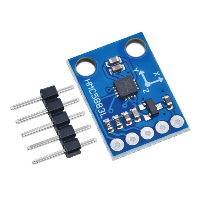
- Accelerometer With Compass Magnetometer Sensor GY-273 3V-5V QMC5883l Triple Axis
- Gyro+Accelerometer
Features:
- Low noise, high-accuracy 3-axis magnetic field sensing
- I2C digital communication interface (100 kHz / 400 kHz)
- High resolution 16-bit ADC output
- Selectable magnetic sensitivity ±2mG to ±8G
- Integrated data-ready interrupt pin (DRDY)
- Low current consumption (75 µA typical active mode)
- Fast acquisition time: 6 ms
- Compact design with standard 2.54mm pin spacing
- Operating temperature: -30°C to +85°C
Specifications:
| Parameter | QMC5883L |
|---|---|
| Voltage Supply (Vs) | 2.16V ~ 3.6V |
| Interface Voltage (VDDIO) | 1.65V ~ 3.6V |
| Absolute Max VDD/VDDIO | -0.3V ~ 5.4V |
| Interface | I2C |
| I2C Address (R/W) | 0x0D |
| I2C Rates | 100 kHz / 400 kHz |
| ADC Resolution | 16 bits |
| Measurement Range | ±2mG to ±8G |
| Survivable Gauss | 50,000G |
| Acquisition Time | 6 ms |
| Active Current | 75 µA to 850 µA |
| Peak Active Current | 2.6 mA |
| Standby Current | 3 µA |
| Operating Temp. | -30°C to +85°C |
Working Principle:
The QMC5883L uses the Anisotropic Magnetoresistance (AMR) effect to detect magnetic fields. When a magnetic field is present, it alters the resistance of a ferrous sensing element inside the chip. This resistance change, due to Lorentz force interaction, is measured and converted into a digital signal via an onboard ADC. This allows the module to sense direction and field strength in all three axes (X, Y, Z).
Pinout:
- VCC: Power supply (3.3V to 5V)
- GND: Ground
- SCL: I2C clock line
- SDA: I2C data line
- DRDY: Data Ready output (optional)
Wiring with Arduino UNO:
- VCC → 5V
- GND → GND
- SCL → A5
- SDA → A4
Sample Arduino Code:
#include <Wire.h>

#define addr 0x1E // I2C address for QMC5883L

void setup() {
  Serial.begin(9600);
  Serial.println("QMC5883L Magnetometer Initialization");
  Wire.begin();

  Wire.beginTransmission(addr);
  Wire.write(0x02); // Mode Register
  Wire.write(0x00); // Continuous measurement mode
  Wire.endTransmission();
}

void loop() {
  int x, y, z;

  // Start reading from register 3
  Wire.beginTransmission(addr);
  Wire.write(0x03);
  Wire.endTransmission();

  // Read 6 bytes of data
  Wire.requestFrom(addr, 6);
  if (Wire.available() >= 6) {
    x = Wire.read() << 8 | Wire.read();
    z = Wire.read() << 8 | Wire.read();
    y = Wire.read() << 8 | Wire.read();

    Serial.print("X: "); Serial.println(x);
    Serial.print("Y: "); Serial.println(y);
    Serial.print("Z: "); Serial.println(z);
    Serial.println();
  }

  delay(1000);
}
Applications:
- Digital compasses
- Robotics navigation
- Orientation tracking in drones
- Magnetic field mapping
- Wearable direction-sensing devices
- Educational sensor experiments