Features:
- 3 selectable full scales: ±250, ±500, ±2000 DPS
- I2C/SPI digital interface for versatile connectivity
- 16-bit output for high-resolution measurements
- 8-bit temperature data output
- Interrupt and Data Ready output pins
- Stable performance over time and temperature
- Supply voltage range: 3.3V - 5V
- Embedded FIFO buffer for efficient data handling
- Wide operating temperature: -40°C to +85°C
- Compact size: 16mm x 17mm
Principle of Work:
Based on Coriolis acceleration, the internal vibrating MEMS element deflects as the module rotates, generating an electrical signal proportional to the angular velocity. This allows the module to detect rotation around the X, Y, and Z axes. Temperature sensing ensures accuracy by compensating for thermal drift.
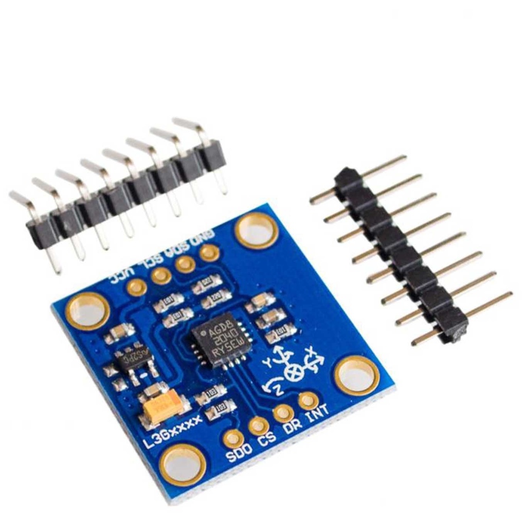
Pinout:
- VCC: Power supply (2.4V–3.6V)
- GND: Ground
- SDA: I2C data line
- SCL: I2C clock line
- CS: Chip Select for SPI
- SDO: SPI data output
- INT1: Interrupt output 1
- DR: Data Ready output
Applications:
- Robotics motion tracking
- Drone stabilization and orientation
- Gaming and VR head tracking
- Navigation and positioning
- Industrial machinery monitoring
- Wearables and motion sensing devices
Circuit Diagram:
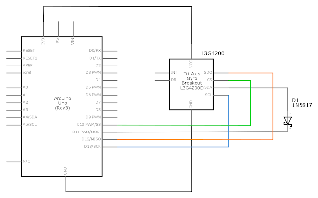
Wiring to Arduino:
- GND → GND
- VCC → 5V
- SDA → A4
- SCL → A5
- SDA ← IN5817 diode cathode; anode → Arduino pin 11
Library:
No external library required.
Example Code (SPI):
#include <SPI.h>

const int CS_Pin = 10;
const float K = 8.75;

void setup() {
  Serial.begin(115200);
  pinMode(CS_Pin, OUTPUT);
  digitalWrite(CS_Pin, HIGH);
  SPI.begin();
  SPI.setBitOrder(MSBFIRST);
  SPI.setDataMode(SPI_MODE3);
  configureGyroscope();
}

void loop() {
  int x = readAxis(0x28);
  int y = readAxis(0x2A);
  int z = readAxis(0x2C);
  Serial.println(String(K*x) + " " + String(K*y) + " " + String(K*z));
  delay(10);
}

void configureGyroscope() {
  writeRegister(0x21, 0x09);
  writeRegister(0x23, 0x80);
  writeRegister(0x20, 0xEF);
}

int readAxis(byte address) {
  digitalWrite(CS_Pin, LOW);
  SPI.transfer(0xE8);
  SPI.transfer(address);
  int value = SPI.transfer(0) | (SPI.transfer(0) << 8);
  digitalWrite(CS_Pin, HIGH);
  return value;
}

void writeRegister(byte address, byte value) {
  digitalWrite(CS_Pin, LOW);
  SPI.transfer(address);
  SPI.transfer(value);
  digitalWrite(CS_Pin, HIGH);
}
Technical Details:
- Sensor: L3G4200D
- Gyroscope range: ±250/±500/±2000 dps
- Sensitivity: 8.75/17.5/70 LSB/dps
- Resolution: 16-bit
- Data rates: 100–800 Hz
- Interfaces: I2C and SPI
- Supply Voltage: 3.3–5V
- Operating Temp: -40°C to +85°C
- Size: 16mm × 17mm
- Weight: 2.9g
Resources:
Comparisons:
Compared to the MPU6050, the GY-50 L3G4200D offers lower power consumption and cost, but lower resolution and narrower measurement ranges. The MPU6050 includes both accelerometer and gyroscope in one, supports higher sensitivity, and is generally better for high-precision applications like gaming and UAVs, while the GY-50 is ideal for cost-effective and low-power projects.
Features:
- 3 selectable full scales: ±250, ±500, ±2000 DPS
- I2C/SPI digital interface for versatile connectivity
- 16-bit output for high-resolution measurements
- 8-bit temperature data output
- Interrupt and Data Ready output pins
- Stable performance over time and temperature
- Supply voltage range: 3.3V - 5V
- Embedded FIFO buffer for efficient data handling
- Wide operating temperature: -40°C to +85°C
- Compact size: 16mm x 17mm
Principle of Work:
Based on Coriolis acceleration, the internal vibrating MEMS element deflects as the module rotates, generating an electrical signal proportional to the angular velocity. This allows the module to detect rotation around the X, Y, and Z axes. Temperature sensing ensures accuracy by compensating for thermal drift.
Pinout:
- VCC: Power supply (2.4V–3.6V)
- GND: Ground
- SDA: I2C data line
- SCL: I2C clock line
- CS: Chip Select for SPI
- SDO: SPI data output
- INT1: Interrupt output 1
- DR: Data Ready output
Applications:
- Robotics motion tracking
- Drone stabilization and orientation
- Gaming and VR head tracking
- Navigation and positioning
- Industrial machinery monitoring
- Wearables and motion sensing devices
Circuit Diagram:
Wiring to Arduino:
- GND → GND
- VCC → 5V
- SDA → A4
- SCL → A5
- SDA ← IN5817 diode cathode; anode → Arduino pin 11
Library:
No external library required.
Example Code (SPI):
#include <SPI.h>

const int CS_Pin = 10;
const float K = 8.75;

void setup() {
  Serial.begin(115200);
  pinMode(CS_Pin, OUTPUT);
  digitalWrite(CS_Pin, HIGH);
  SPI.begin();
  SPI.setBitOrder(MSBFIRST);
  SPI.setDataMode(SPI_MODE3);
  configureGyroscope();
}

void loop() {
  int x = readAxis(0x28);
  int y = readAxis(0x2A);
  int z = readAxis(0x2C);
  Serial.println(String(K*x) + " " + String(K*y) + " " + String(K*z));
  delay(10);
}

void configureGyroscope() {
  writeRegister(0x21, 0x09);
  writeRegister(0x23, 0x80);
  writeRegister(0x20, 0xEF);
}

int readAxis(byte address) {
  digitalWrite(CS_Pin, LOW);
  SPI.transfer(0xE8);
  SPI.transfer(address);
  int value = SPI.transfer(0) | (SPI.transfer(0) << 8);
  digitalWrite(CS_Pin, HIGH);
  return value;
}

void writeRegister(byte address, byte value) {
  digitalWrite(CS_Pin, LOW);
  SPI.transfer(address);
  SPI.transfer(value);
  digitalWrite(CS_Pin, HIGH);
}
Technical Details:
- Sensor: L3G4200D
- Gyroscope range: ±250/±500/±2000 dps
- Sensitivity: 8.75/17.5/70 LSB/dps
- Resolution: 16-bit
- Data rates: 100–800 Hz
- Interfaces: I2C and SPI
- Supply Voltage: 3.3–5V
- Operating Temp: -40°C to +85°C
- Size: 16mm × 17mm
- Weight: 2.9g
Resources:
Comparisons:
Compared to the MPU6050, the GY-50 L3G4200D offers lower power consumption and cost, but lower resolution and narrower measurement ranges. The MPU6050 includes both accelerometer and gyroscope in one, supports higher sensitivity, and is generally better for high-precision applications like gaming and UAVs, while the GY-50 is ideal for cost-effective and low-power projects.