- All products
- Sensors & Modules
- Magnetic
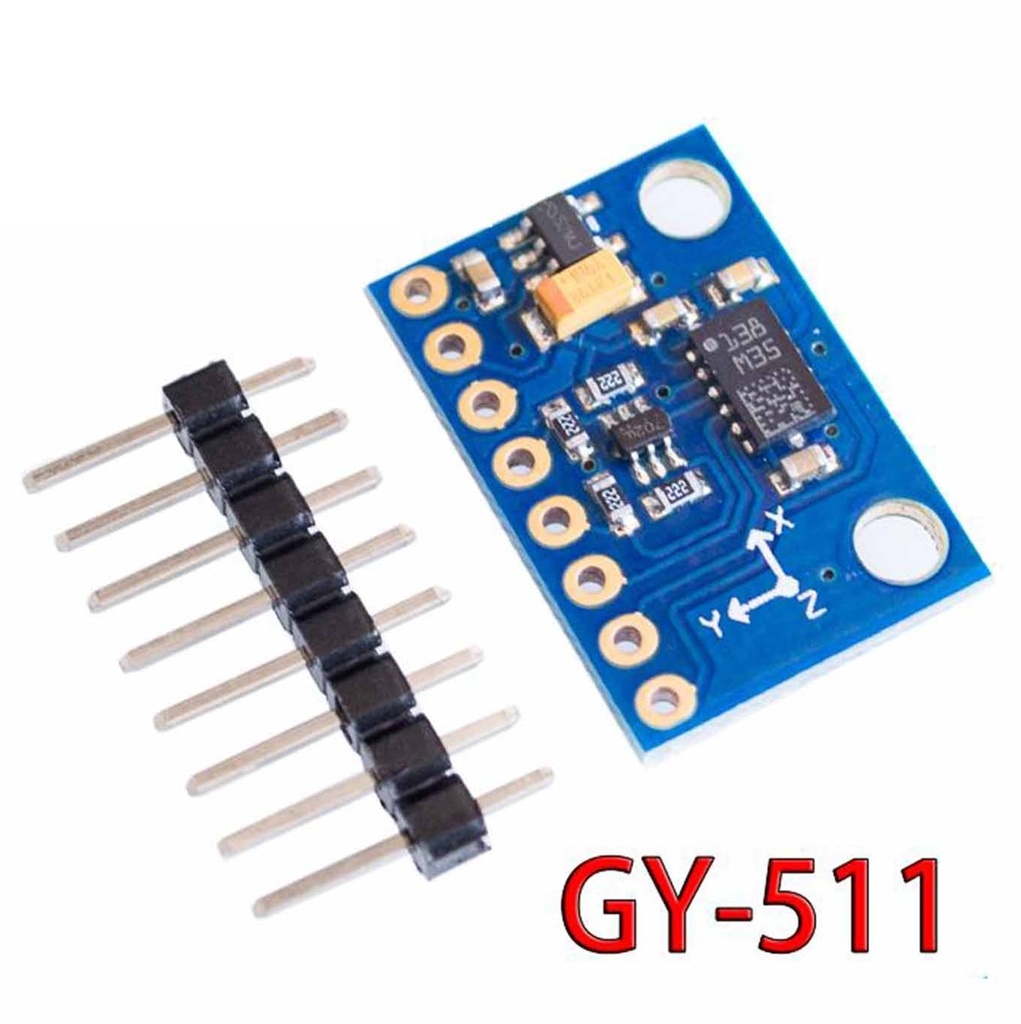
- Accelerometer 3 Axis Compass Sensor Module GY-511 LSM303
- Magnetic
Specifications:
- Power supply: 3-5V
- Model: GY-511
- 3 magnetic field channels and 3 acceleration channels
- Magnetic field full scale range: ±1.3 to ±8.1 gauss
- Linear acceleration full scale: ±2g, ±4g, ±8g, ±16g
- 16-bit data output resolution
- I²C serial communication interface
- Power-down and low-power modes supported
- 2 programmable interrupt generators (free-fall, motion detection)
- Embedded temperature sensor
- Built-in FIFO buffer
- 6D/4D orientation detection
- Chip includes 12-bit ADC with 16-bit data output
- Pin pitch: 2.54 mm
- Module size: 20.5mm × 14.5mm
Applications:
- Tilt-compensated digital compasses
- Map rotation and position detection
- Motion-triggered functions
- Free-fall detection and impact logging
- Click and double-click gesture recognition
- Pedometers and fitness trackers
- Power-saving features for handheld devices
- Display orientation adjustment
- Gaming and virtual reality input
- Vibration monitoring and compensation
LSM303DLHC GY-511 Module Pinout:
| Pin | Name | Description |
|---|---|---|
| 1 | GND | Ground connection to complete the circuit |
| 2 | 3.3V | Power supply input (recommended 3.3V) |
| 3 | SDA | I2C Serial Data line |
| 4 | SCL | I2C Serial Clock line |
| 5 | INT1 | Inertial Interrupt 1 (external interrupt request) |
| 6 | INT2 | Inertial Interrupt 2 (external interrupt request) |
| 7 | DRDY | Data Ready indicator output |
| 8 | VIN | Main power supply input (2.5V to 5.5V) |
Arduino Code Example for LSM303 Module:
Before using the code, download and install the LSM303 library.
#include <Wire.h>
#include <LSM303.h>

LSM303 compass;
LSM303::vector running_min = {32767, 32767, 32767};
LSM303::vector running_max = {-32768, -32768, -32768};
char report[80];

void setup() {
  Serial.begin(9600);
  Wire.begin();
  compass.init();
  compass.enableDefault();
}

void loop() {
  compass.read();

  running_min.x = min(running_min.x, compass.m.x);
  running_min.y = min(running_min.y, compass.m.y);
  running_min.z = min(running_min.z, compass.m.z);

  running_max.x = max(running_max.x, compass.m.x);
  running_max.y = max(running_max.y, compass.m.y);
  running_max.z = max(running_max.z, compass.m.z);

  snprintf(report, sizeof(report),
    "min: {%+6d, %+6d, %+6d} max: {%+6d, %+6d, %+6d}",
    running_min.x, running_min.y, running_min.z,
    running_max.x, running_max.y, running_max.z);

  Serial.println(report);
  delay(100);
}