Principle of Work:
- Multiplexing: Selects one input line out of eight to forward to the common output line. For example, setting select pins A/B/C to binary 010 (decimal 2) activates channel 2 (pin 15), routing its signal to the common output (pin 3).
- Demultiplexing: Routes a single input signal at the common pin to one of the eight output channels based on select pins. For instance, setting A/B/C to 111 (decimal 7) activates channel 7 (pin 4), forwarding the common input signal to it.
- Bi-directional Signal Flow: The device supports signals flowing in either direction between the common pin and the selected channel, achieved using complementary MOSFET pairs providing about 80Ω resistance when selected.
- Applications: Widely used to expand the number of analog inputs available to microcontrollers like Arduino, for signal routing, or switching among multiple sensors or outputs.


Features:
- Three digital select inputs (S0, S1, S2) for channel selection, allowing 8 different channels.
- Eight independent I/O pins (Y0 to Y7) usable as inputs or outputs.
- Common input/output pin (Z) for selected channel connection.
- Digital enable input (E) disables all switches and puts output in high-impedance state when high.
- Integrated terminal diodes for input protection and current limiting.
- Wide voltage range (2V to 10V) supports diverse analog and digital signals.
- Low power consumption, suitable for battery-powered and portable devices.
Specifications:
| Model | 74HCT4051 |
|---|---|
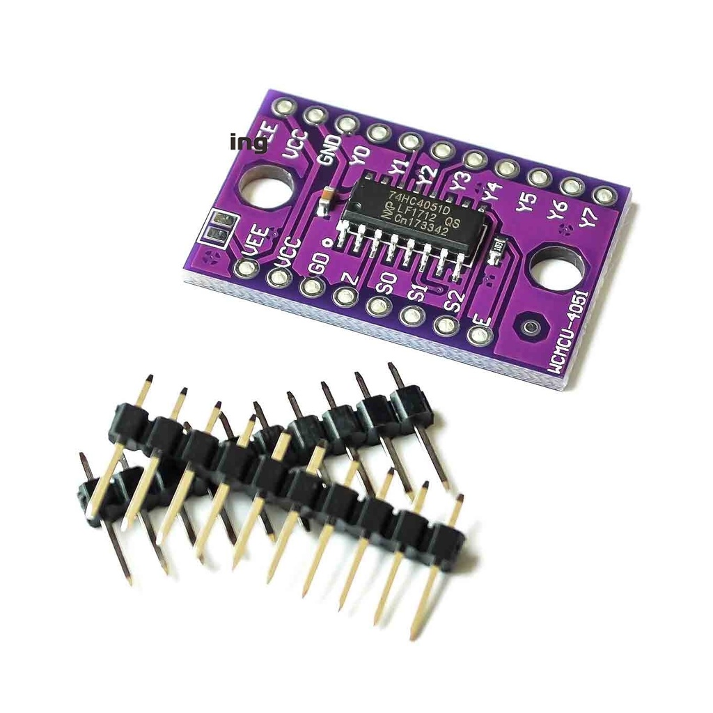
| Color | Purple |
| Dimensions | 29.5 x 18.5 x 3 mm |
| Voltage Range | 2V - 10V |
| On-Resistance | ~125 Ω (typical) |
Applications:
- Analog signal multiplexing: Selecting one of multiple analog inputs for processing or measurement.
- Digital signal multiplexing: Switching digital signals for microcontroller inputs or outputs.
- Data acquisition systems: Expanding analog input channels.
- Instrumentation and measurement: Routing signals to measurement circuits.
- Industrial control: Switching sensor or actuator signals for flexible process control.
Pin Connections:
| Pin | Description |
|---|---|
| Y0 - Y7 | Independent input/output pins (channels) |
| GND | Ground (0V) |
| S0, S1, S2 | Digital select control inputs (3-bit binary channel selector) |
| Z | Common input/output pin (connected to the selected channel) |
| VCC | Positive power supply voltage (2V to 10V) |
| VEE | Negative supply voltage (usually connected to GND) |
| E | Active low enable input (low = enabled, high = disabled) |

Sample Project:
Circuit Setup:
- Connect S0, S1, S2 to Arduino digital pins 2, 3, and 4 respectively.
- Connect common pin Z to Arduino analog input A0.
- Connect VCC to 5V and GND to Ground.
- Keep VEE connected to GND (default).
- Connect each Y0-Y7 pin to an LED with a 330Ω resistor in series to ground for visual indication.

Code Example (Arduino):
/******************************************************************************
 Mux_Analog_Input SparkFun Multiplexer Analog Input Example

 Demonstrates reading eight analog inputs with one Arduino ADC pin
 using 74HC4051 multiplexer.

 Hardware Connections:
 MUX      Arduino
 S0  ----- Pin 2
 S1  ----- Pin 3
 S2  ----- Pin 4
 Z   ----- A0 (Analog input)
 VCC ----- 5V
 GND ----- GND
 VEE ----- GND (jumpered)

 Y0-Y7: connect to analog sensors or potentiometers
******************************************************************************/

const int selectPins[3] = {2, 3, 4}; // S0, S1, S2 pins
const int zInput = A0;                // Common output input pin

void setup() {
  Serial.begin(9600);
  // Initialize select pins as outputs
  for (int i = 0; i < 3; i++) {
    pinMode(selectPins[i], OUTPUT);
    digitalWrite(selectPins[i], LOW);
  }
  pinMode(zInput, INPUT);

  Serial.println("Y0\tY1\tY2\tY3\tY4\tY5\tY6\tY7");
  Serial.println("---\t---\t---\t---\t---\t---\t---\t---");
}

void loop() {
  for (byte channel = 0; channel < 8; channel++) {
    selectMuxPin(channel);
    int sensorValue = analogRead(zInput);
    Serial.print(sensorValue);
    Serial.print("\t");
  }
  Serial.println();
  delay(1000);
}

void selectMuxPin(byte channel) {
  for (int i = 0; i < 3; i++) {
    digitalWrite(selectPins[i], (channel >> i) & 0x01);
  }
}
Notes:
- No external libraries required to use this module.
- Multiplexer channels are bi-directional, but typically used for analog input multiplexing.
- Ensure proper wiring of VEE to GND to avoid device malfunction.
Principle of Work:
- Multiplexing: Selects one input line out of eight to forward to the common output line. For example, setting select pins A/B/C to binary 010 (decimal 2) activates channel 2 (pin 15), routing its signal to the common output (pin 3).
- Demultiplexing: Routes a single input signal at the common pin to one of the eight output channels based on select pins. For instance, setting A/B/C to 111 (decimal 7) activates channel 7 (pin 4), forwarding the common input signal to it.
- Bi-directional Signal Flow: The device supports signals flowing in either direction between the common pin and the selected channel, achieved using complementary MOSFET pairs providing about 80Ω resistance when selected.
- Applications: Widely used to expand the number of analog inputs available to microcontrollers like Arduino, for signal routing, or switching among multiple sensors or outputs.
Features:
- Three digital select inputs (S0, S1, S2) for channel selection, allowing 8 different channels.
- Eight independent I/O pins (Y0 to Y7) usable as inputs or outputs.
- Common input/output pin (Z) for selected channel connection.
- Digital enable input (E) disables all switches and puts output in high-impedance state when high.
- Integrated terminal diodes for input protection and current limiting.
- Wide voltage range (2V to 10V) supports diverse analog and digital signals.
- Low power consumption, suitable for battery-powered and portable devices.
Specifications:
| Model | 74HCT4051 |
|---|---|
| Color | Purple |
| Dimensions | 29.5 x 18.5 x 3 mm |
| Voltage Range | 2V - 10V |
| On-Resistance | ~125 Ω (typical) |
Applications:
- Analog signal multiplexing: Selecting one of multiple analog inputs for processing or measurement.
- Digital signal multiplexing: Switching digital signals for microcontroller inputs or outputs.
- Data acquisition systems: Expanding analog input channels.
- Instrumentation and measurement: Routing signals to measurement circuits.
- Industrial control: Switching sensor or actuator signals for flexible process control.
Pin Connections:
| Pin | Description |
|---|---|
| Y0 - Y7 | Independent input/output pins (channels) |
| GND | Ground (0V) |
| S0, S1, S2 | Digital select control inputs (3-bit binary channel selector) |
| Z | Common input/output pin (connected to the selected channel) |
| VCC | Positive power supply voltage (2V to 10V) |
| VEE | Negative supply voltage (usually connected to GND) |
| E | Active low enable input (low = enabled, high = disabled) |
Sample Project:
Circuit Setup:
- Connect S0, S1, S2 to Arduino digital pins 2, 3, and 4 respectively.
- Connect common pin Z to Arduino analog input A0.
- Connect VCC to 5V and GND to Ground.
- Keep VEE connected to GND (default).
- Connect each Y0-Y7 pin to an LED with a 330Ω resistor in series to ground for visual indication.
Code Example (Arduino):
/******************************************************************************
 Mux_Analog_Input SparkFun Multiplexer Analog Input Example

 Demonstrates reading eight analog inputs with one Arduino ADC pin
 using 74HC4051 multiplexer.

 Hardware Connections:
 MUX      Arduino
 S0  ----- Pin 2
 S1  ----- Pin 3
 S2  ----- Pin 4
 Z   ----- A0 (Analog input)
 VCC ----- 5V
 GND ----- GND
 VEE ----- GND (jumpered)

 Y0-Y7: connect to analog sensors or potentiometers
******************************************************************************/

const int selectPins[3] = {2, 3, 4}; // S0, S1, S2 pins
const int zInput = A0;                // Common output input pin

void setup() {
  Serial.begin(9600);
  // Initialize select pins as outputs
  for (int i = 0; i < 3; i++) {
    pinMode(selectPins[i], OUTPUT);
    digitalWrite(selectPins[i], LOW);
  }
  pinMode(zInput, INPUT);

  Serial.println("Y0\tY1\tY2\tY3\tY4\tY5\tY6\tY7");
  Serial.println("---\t---\t---\t---\t---\t---\t---\t---");
}

void loop() {
  for (byte channel = 0; channel < 8; channel++) {
    selectMuxPin(channel);
    int sensorValue = analogRead(zInput);
    Serial.print(sensorValue);
    Serial.print("\t");
  }
  Serial.println();
  delay(1000);
}

void selectMuxPin(byte channel) {
  for (int i = 0; i < 3; i++) {
    digitalWrite(selectPins[i], (channel >> i) & 0x01);
  }
}
Notes:
- No external libraries required to use this module.
- Multiplexer channels are bi-directional, but typically used for analog input multiplexing.
- Ensure proper wiring of VEE to GND to avoid device malfunction.