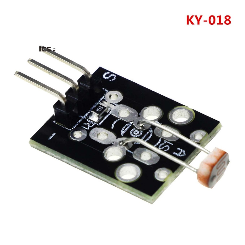
LDR Ky-018 Photosensitive Sensor
The KY-018 Photoresistor Module is a simple and effective analog light sensor that measures ambient light intensity using a light-dependent resistor (LDR). It changes resistance based on light levels—resistance decreases in brighter light and increases in darkness. The analog output can be easily read by microcontrollers like Arduino, ESP32, Raspberry Pi, and others, making it suitable for a variety of light-sensing applications.
Package Includes:
- 1 x KY-018 Photoresistor Light Sensor Module
Features
- Utilizes a sensitive LDR (Light-Dependent Resistor)
- Input Voltage: 3.3V – 5V
- Analog Voltage Output (AO)
- Fixed mounting holes for easy installation
- Compatible with Arduino, ESP32, and other microcontrollers
Principle of Operation
The LDR is a high-resistance semiconductor component (often cadmium sulfide) with a zigzag pattern exposed to light. When light photons hit the surface, valence electrons gain energy and jump to the conduction band, increasing current flow and decreasing resistance. The more light, the lower the resistance and the higher the analog voltage output. This principle enables light-level detection.
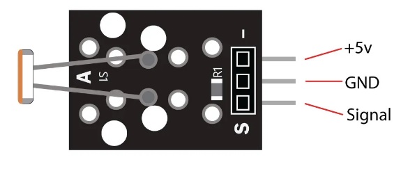
Pinout Configuration
| Pin | Description |
|---|---|
| S | Analog Output (to analog pin, e.g., A0) |
| + | Power Supply (3.3V – 5V) |
| – | Ground (GND) |
Applications
- Ambient light level detection
- Solar tracking systems
- Laser-based light barriers
- Optocouplers and light-sensitive triggers
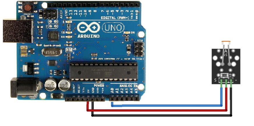
Circuit Diagram
Connect the sensor's:
- VCC (+) to 5V
- GND (–) to GND
- S to Analog Input (e.g., A0 or A5)
Library
No external library is required to use the KY-018 module with Arduino.
Sample Arduino Code
int sensorPin = A5; // Connect signal pin S to A5

void setup() {
  Serial.begin(9600); // Initialize Serial Monitor
}

void loop() {
  int rawValue = analogRead(sensorPin);
  float voltage = rawValue * (5.0 / 1023.0) * 1000; // Convert to mV
  float resistance = 10000 * (voltage / (5000.0 - voltage)); // Calculate resistance

  Serial.print("Voltage: ");
  Serial.print(voltage);
  Serial.print(" mV, Resistance: ");
  Serial.print(resistance);
  Serial.println(" Ohm");
  Serial.println("---------------------------------------");
  delay(500); // Delay between readings
}
How the Code Works
- Reads analog voltage from the sensor
- Calculates actual voltage and corresponding resistance
- Prints voltage and resistance to Serial Monitor
After uploading the code, open the Serial Monitor and expose the sensor to light. The resistance and voltage will change in real-time as light intensity varies.
Technical Specifications
- Operating Voltage: 3.3V – 5V
- Output Voltage: Analog 0 – 5V
- Fixed Known Resistor: 10kΩ
- Dimensions: 21mm x 15mm x 6mm
Additional Notes
Compared to a bare LDR sensor, the KY-018 module is more beginner-friendly because it includes necessary resistors and mounting support. However, it only provides analog output and lacks advanced features like amplification or digital trigger (Schmitt trigger), which are found in other light sensor modules.
Features
- Utilizes a sensitive LDR (Light-Dependent Resistor)
- Input Voltage: 3.3V – 5V
- Analog Voltage Output (AO)
- Fixed mounting holes for easy installation
- Compatible with Arduino, ESP32, and other microcontrollers
Principle of Operation
The LDR is a high-resistance semiconductor component (often cadmium sulfide) with a zigzag pattern exposed to light. When light photons hit the surface, valence electrons gain energy and jump to the conduction band, increasing current flow and decreasing resistance. The more light, the lower the resistance and the higher the analog voltage output. This principle enables light-level detection.
Pinout Configuration
| Pin | Description |
|---|---|
| S | Analog Output (to analog pin, e.g., A0) |
| + | Power Supply (3.3V – 5V) |
| – | Ground (GND) |
Applications
- Ambient light level detection
- Solar tracking systems
- Laser-based light barriers
- Optocouplers and light-sensitive triggers
Circuit Diagram
Connect the sensor's:
- VCC (+) to 5V
- GND (–) to GND
- S to Analog Input (e.g., A0 or A5)
Library
No external library is required to use the KY-018 module with Arduino.
Sample Arduino Code
int sensorPin = A5; // Connect signal pin S to A5

void setup() {
  Serial.begin(9600); // Initialize Serial Monitor
}

void loop() {
  int rawValue = analogRead(sensorPin);
  float voltage = rawValue * (5.0 / 1023.0) * 1000; // Convert to mV
  float resistance = 10000 * (voltage / (5000.0 - voltage)); // Calculate resistance

  Serial.print("Voltage: ");
  Serial.print(voltage);
  Serial.print(" mV, Resistance: ");
  Serial.print(resistance);
  Serial.println(" Ohm");
  Serial.println("---------------------------------------");
  delay(500); // Delay between readings
}
How the Code Works
- Reads analog voltage from the sensor
- Calculates actual voltage and corresponding resistance
- Prints voltage and resistance to Serial Monitor
After uploading the code, open the Serial Monitor and expose the sensor to light. The resistance and voltage will change in real-time as light intensity varies.
Technical Specifications
- Operating Voltage: 3.3V – 5V
- Output Voltage: Analog 0 – 5V
- Fixed Known Resistor: 10kΩ
- Dimensions: 21mm x 15mm x 6mm
Additional Notes
Compared to a bare LDR sensor, the KY-018 module is more beginner-friendly because it includes necessary resistors and mounting support. However, it only provides analog output and lacks advanced features like amplification or digital trigger (Schmitt trigger), which are found in other light sensor modules.