Main Parameters
- Interface: SPI
- Capacity: 64 Mbit (8 MByte)
- Operating Voltage: 2.7 ~ 3.6 V
- Size: 14 mm × 15 mm
Memory Organization
- 128 Blocks (each block = 64 KBytes)
- Each Block contains 16 Sectors
- Each Sector contains 256 Pages
- Each Page size: 256 Bytes
Features
- Flash bits can only be programmed from 1 to 0; to change bits from 0 to 1 requires an erase cycle.
- Supports SPI communication for simple connection and control.
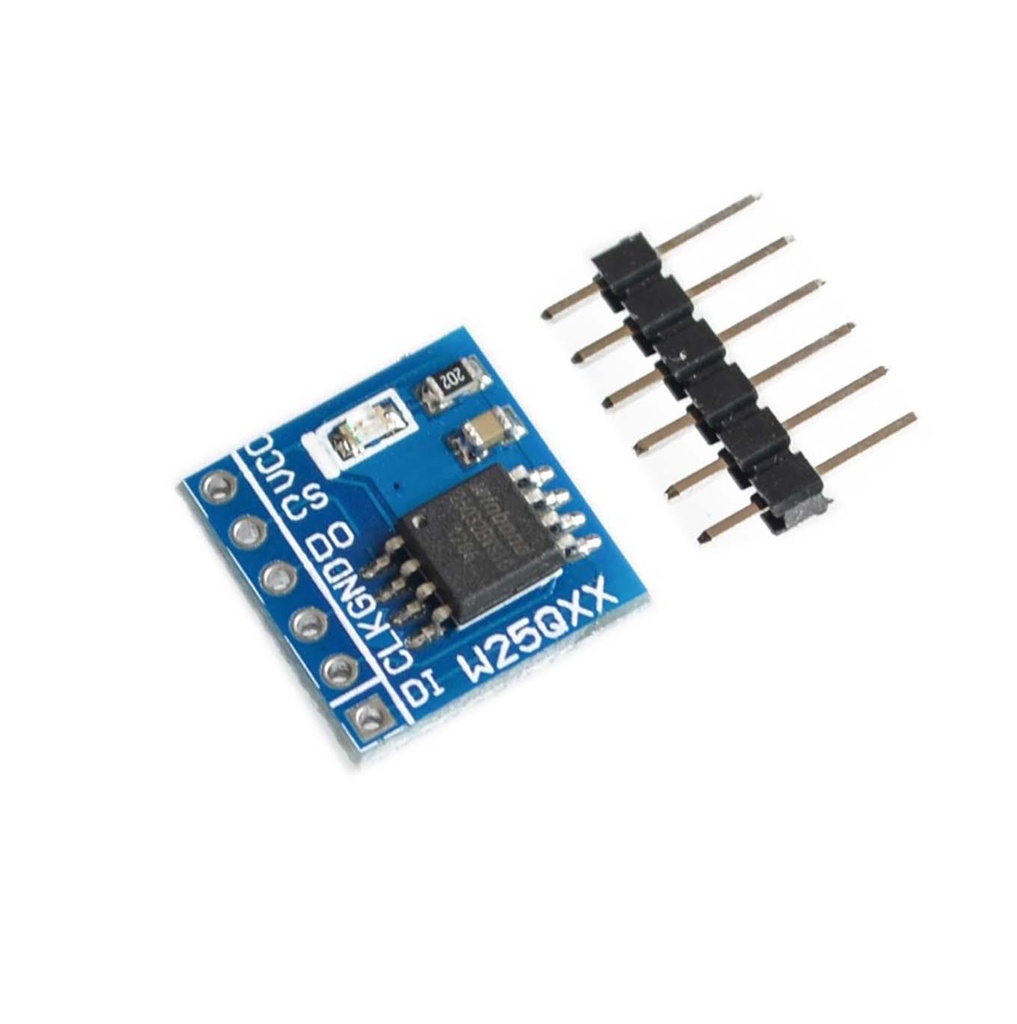
Pin Description
| Pin | Description |
|---|---|
| CS | Chip Select, active low. SPI communication starts when this pin goes low. |
| DO (MISO) | Data Output (Master In Slave Out). Data output on falling edge of clock. |
| WP | Write Protect, active low. When low, memory is read-only; when high, read/write enabled. |
| DI (MOSI) | Data Input (Master Out Slave In). Data input on rising edge of clock. |
| CLK (SCLK) | Serial Clock input. |
| HOLD | Active low. Pauses serial communication when low by setting data output to high impedance. |
| VCC | Power supply, 2.7V to 3.6V. |
| GND | Ground. |
SPI Communication Details
- Supports SPI Mode 0 (CPOL=0, CPHA=0) and Mode 3 (CPOL=1, CPHA=1).
- Data is captured on the rising edge of SCLK, output data changes on the falling edge.
Data Format and Transfer Speed
- Data size is 8 bits.
- Supports standard mode transfer up to 80 Mbps.
- Fast mode up to 160 Mbps and high-speed mode up to 320 Mbps.
Arduino Library for W25Q64 Flash Memory Module
There are Arduino libraries available for easy SPI communication and memory management. You can find libraries and example codes by searching for W25Q64 Arduino library or from reliable repositories like GitHub.
Example Image of Pinout

Usage
The W25Q64 module is typically used to store program code or large data such as firmware updates, audio, images, or logs in MCUs that have insufficient internal flash memory. With simple SPI wiring, it can easily expand your system's storage capacity.
Main Parameters
- Interface: SPI
- Capacity: 64 Mbit (8 MByte)
- Operating Voltage: 2.7 ~ 3.6 V
- Size: 14 mm × 15 mm
Memory Organization
- 128 Blocks (each block = 64 KBytes)
- Each Block contains 16 Sectors
- Each Sector contains 256 Pages
- Each Page size: 256 Bytes
Features
- Flash bits can only be programmed from 1 to 0; to change bits from 0 to 1 requires an erase cycle.
- Supports SPI communication for simple connection and control.
Pin Description
| Pin | Description |
|---|---|
| CS | Chip Select, active low. SPI communication starts when this pin goes low. |
| DO (MISO) | Data Output (Master In Slave Out). Data output on falling edge of clock. |
| WP | Write Protect, active low. When low, memory is read-only; when high, read/write enabled. |
| DI (MOSI) | Data Input (Master Out Slave In). Data input on rising edge of clock. |
| CLK (SCLK) | Serial Clock input. |
| HOLD | Active low. Pauses serial communication when low by setting data output to high impedance. |
| VCC | Power supply, 2.7V to 3.6V. |
| GND | Ground. |
SPI Communication Details
- Supports SPI Mode 0 (CPOL=0, CPHA=0) and Mode 3 (CPOL=1, CPHA=1).
- Data is captured on the rising edge of SCLK, output data changes on the falling edge.
Data Format and Transfer Speed
- Data size is 8 bits.
- Supports standard mode transfer up to 80 Mbps.
- Fast mode up to 160 Mbps and high-speed mode up to 320 Mbps.
Arduino Library for W25Q64 Flash Memory Module
There are Arduino libraries available for easy SPI communication and memory management. You can find libraries and example codes by searching for W25Q64 Arduino library or from reliable repositories like GitHub.
Example Image of Pinout
Usage
The W25Q64 module is typically used to store program code or large data such as firmware updates, audio, images, or logs in MCUs that have insufficient internal flash memory. With simple SPI wiring, it can easily expand your system's storage capacity.