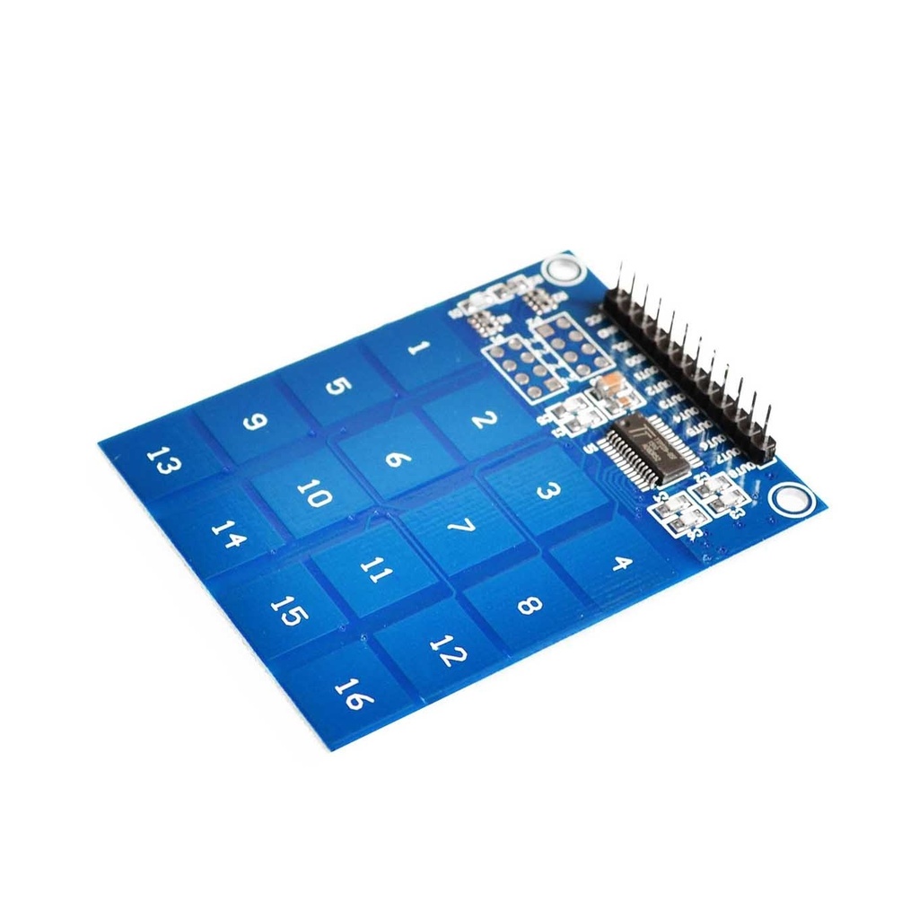
Features
- Based on TTP229 IC
- 16 capacitive touch keys
- Selectable 8-key or 16-key mode
- Separate outputs for 8 keys in 8-key mode
- Supports toggle or momentary output modes
- Configurable output polarity (active-high or active-low)
- 0.5 second startup calibration delay
- Low standby current (2.5μA at 3V)
- On-board power indicator LED
Specifications
- Operating Voltage: 2.4V – 5.5V
- Standby Current: 2.5μA @ 3V
- Operating Modes: 8 or 16 key
- PCB Size: 49.3mm x 64.5mm
Pinout
- VCC – Supply Voltage (2.4V to 5.5V)
- GND – Ground
- SCL – Serial Clock Input
- SDO – Serial Data Output
- OUT 1 – Key 1 State
- OUT 2 – Key 2 State
- OUT 3 – Key 3 State
- OUT 4 – Key 4 State
- OUT 5 – Key 5 State
- OUT 6 – Key 6 State
- OUT 7 – Key 7 State
- OUT 8 – Key 8 State
Example Arduino Wiring (16-Key Mode)
- TTP229 VCC to Arduino VCC
- TTP229 GND to Arduino GND
- TTP229 SCL to Arduino Pin 2
- TTP229 SDO to Arduino Pin 3
- TTP229 TP2 to GND via 1 MΩ resistor (only needed for some modules)
Important: Reconnect power after changing jumper settings for changes to take effect.
Example Arduino Code
// TTP229 16-Key Touch Sensor Example
#include <TTP229.h>
const int SCL_PIN = 2; // Clock Pin
const int SDO_PIN = 3; // Data Pin
TTP229 ttp229(SCL_PIN, SDO_PIN);
void setup() {
Serial.begin(115200);
Serial.println("Start Touching One Key At a Time!");
}
void loop() {
uint8_t key = ttp229.ReadKey16(); // Blocking read
if (key)
Serial.println(key);
// Non-blocking alternative:
// uint8_t key = ttp229.GetKey16();
// Serial.println(key);
}