Specifications
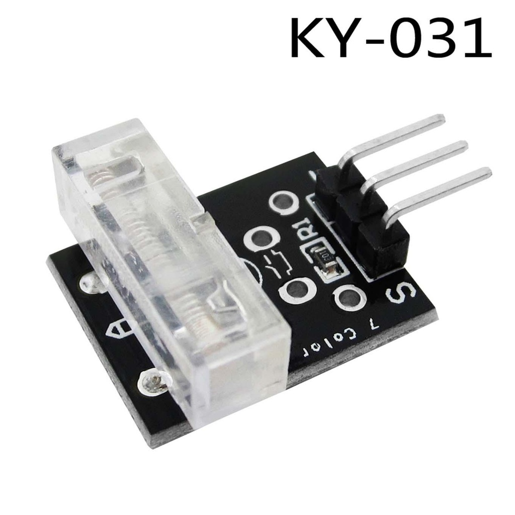
- Model: KY-031
- Maximum Operating Voltage: 5V
- Module Output Type: ON/OFF (Digital)
- Output Signal Category: Digital Sensor
- Sensor Category: Vibration and Shock Sensors
- Working Principle: Mechanical Vibration Sensor
- Compact Size: The module measures 27mm x 15mm x 9mm, making it easy to integrate into various projects.
Understanding How the Knock Sensor Works
Internal Schematic of the Knock Sensor
To truly grasp the functionality of the KY-031 Knock Sensor Module, it's helpful to visualize its internal structure. The image below provides a simplified representation of the module's electrical schematic, revealing its core components.
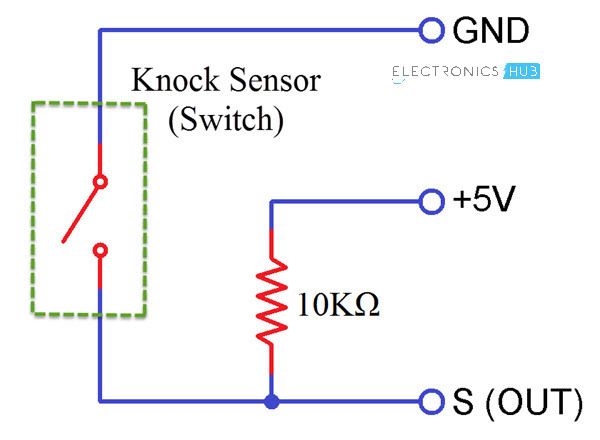
Looking at the schematic, you'll see that the knock sensor is essentially a simple switch combined with a resistor. The "vibrating spring" within the module acts as a momentary switch. Under normal conditions, when there are no significant shocks or vibrations, this switch remains open. The sensor's signal output pin is connected to this switch and is held HIGH (at or near the supply voltage) by a 10K Ohm pull-up resistor. This means that by default, when the sensor is quiet, its output signal is HIGH.
The magic happens when the sensor experiences a physical impact or vibration. The vibrating spring briefly closes the switch, momentarily connecting the signal pin to ground. This action causes the output signal at the 'S' pin to drop to a LOW state. Your microcontroller, like an Arduino, can then detect this rapid transition from HIGH to LOW as an indication of a "knock" or "impact." Once the vibration subsides, the spring returns to its open position, and the output signal goes back to HIGH, thanks to the pull-up resistor.
Interfacing the Knock Sensor with Arduino
Now that we understand the components and the operating principle of the knock sensor, let's move on to integrating it with an Arduino. We'll set up a basic circuit where an LED illuminates when the knock sensor detects a vibration. Additionally, we'll send messages to the Arduino IDE's serial monitor to provide feedback on whether a knock has been detected.
Circuit Diagram for Arduino Interfacing
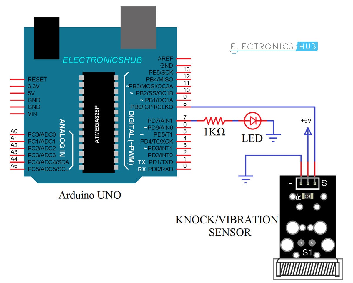
The following image illustrates the precise connections for wiring the KY-031 Knock Sensor Module with an Arduino UNO.
Needed Components
- Arduino UNO board
- KY-031 Knock Sensor Module
- 1K Ohm Resistor (for current limiting with the LED)
- Standard LED (Light Emitting Diode)
Wiring Up the Circuit
Wiring the knock sensor with your Arduino is quite straightforward. Follow these steps for the circuit design:
- Connect the VCC pin of the KY-031 Knock Sensor module to the +5V power output pin on your Arduino UNO.
- Connect the GND pin of the Knock Sensor module to any GND (Ground) pin on your Arduino UNO.
- Connect the signal output pin (labeled 'S') of the Knock Sensor module to Digital I/O pin 8 on your Arduino UNO.
- Finally, connect an LED to Digital Pin 7 of the Arduino UNO. Make sure to place the 1K Ohm current-limiting resistor in series with the longer leg (anode) of the LED. Connect the shorter leg (cathode) of the LED to a GND pin on the Arduino.
Arduino Code:
The following Arduino code is designed to read the digital input from the knock sensor and control the LED accordingly. It also provides useful feedback through the serial monitor, indicating when a knock is detected or when there are no vibrations.
const int knockPin = 8; // Define the digital pin connected to the knock sensor's signal output
const int ledPin = 7; // Define the digital pin connected to the LED
int knockVal = HIGH; // Variable to store the current state read from the knock sensor (initially HIGH)
boolean knockAlarm = false; // A flag to track if a knock alarm is currently active
unsigned long prevKnockTime; // Stores the time (in milliseconds) when the last knock was detected
int knockAlarmTime = 100; // The duration (in milliseconds) for which a knock alarm remains active after detection
void setup() {
 Serial.begin(9600); // Initialize serial communication at a baud rate of 9600 for debugging
 pinMode(ledPin, OUTPUT); // Set the LED pin as an output pin
 pinMode(knockPin, INPUT); // Set the knock sensor pin as an input pin
}
void loop() {
 knockVal = digitalRead(knockPin); // Read the current state of the knock sensor pin
 if (knockVal == LOW) { // If a knock is detected (sensor output goes LOW)
 prevKnockTime = millis(); // Update the time of the last knock
 if (!knockAlarm) { // Check if a knock alarm is not already active
 Serial.println("KNOCK, KNOCK"); // Print a message to the serial monitor
 digitalWrite(ledPin, HIGH); // Turn on the LED
 knockAlarm = true; // Set the knock alarm flag to true
 delay(1000); // Keep the LED on for 1 second (this also acts as a debounce)
 }
 } else { // If no knock is currently being detected (sensor output is HIGH)
 // Check if enough time has passed since the last knock AND if an alarm was previously active
 if ((millis() - prevKnockTime) > knockAlarmTime && knockAlarm) {
 digitalWrite(ledPin, LOW); // Turn off the LED
 Serial.println("No Knocks"); // Print a message to the serial monitor
 knockAlarm = false; // Reset the knock alarm flag
 }
 }
}
How the Code Works
Once you've made all the connections according to the circuit diagram, upload the Arduino code to your board. You can then attach or place the knock sensor on a surface you wish to monitor, such as a door. When a vibration or impact is strong enough for the sensor to detect, its signal output (pin S) will briefly go LOW. Your Arduino, constantly reading this pin, will detect this change.
Upon detection, the Arduino will turn on the connected LED for a set duration (in this case, 1 second) and print "KNOCK, KNOCK" to the serial monitor. If no further significant vibrations are detected within the defined 'knockAlarmTime' (100 milliseconds in this example), the LED will turn off, and the serial monitor will display "No Knocks," indicating that the system has returned to its idle state
Important Considerations
Conclusion on Sensitivity
Through practical experimentation, it's generally observed that the KY-031 Knock Sensor is not an extremely sensitive device. It typically won't detect very light taps or subtle vibrations. Instead, it requires a relatively hard impact or significant vibration to trigger its output. While this characteristic makes it less suitable for applications requiring high sensitivity or subtle movement detection, it's perfectly adequate for specific uses.
Applications
The primary function of the Knock Sensor is to detect significant vibrations or shocks. Given its working principle, this sensor finds its main application in systems like a "Door Knock Monitoring System." In such a setup, when a door receives a noticeable knock, the sensor can trigger various notifications, such as illuminating a light, activating a buzzer, or sending an alert to a connected system. It's an excellent component for simple security alerts or interactive projects where a clear, distinct impact needs to be registered.
Specifications
- Model: KY-031
- Maximum Operating Voltage: 5V
- Module Output Type: ON/OFF (Digital)
- Output Signal Category: Digital Sensor
- Sensor Category: Vibration and Shock Sensors
- Working Principle: Mechanical Vibration Sensor
- Compact Size: The module measures 27mm x 15mm x 9mm, making it easy to integrate into various projects.
Understanding How the Knock Sensor Works
Internal Schematic of the Knock Sensor
To truly grasp the functionality of the KY-031 Knock Sensor Module, it's helpful to visualize its internal structure. The image below provides a simplified representation of the module's electrical schematic, revealing its core components.
Looking at the schematic, you'll see that the knock sensor is essentially a simple switch combined with a resistor. The "vibrating spring" within the module acts as a momentary switch. Under normal conditions, when there are no significant shocks or vibrations, this switch remains open. The sensor's signal output pin is connected to this switch and is held HIGH (at or near the supply voltage) by a 10K Ohm pull-up resistor. This means that by default, when the sensor is quiet, its output signal is HIGH.
The magic happens when the sensor experiences a physical impact or vibration. The vibrating spring briefly closes the switch, momentarily connecting the signal pin to ground. This action causes the output signal at the 'S' pin to drop to a LOW state. Your microcontroller, like an Arduino, can then detect this rapid transition from HIGH to LOW as an indication of a "knock" or "impact." Once the vibration subsides, the spring returns to its open position, and the output signal goes back to HIGH, thanks to the pull-up resistor.
Interfacing the Knock Sensor with Arduino
Now that we understand the components and the operating principle of the knock sensor, let's move on to integrating it with an Arduino. We'll set up a basic circuit where an LED illuminates when the knock sensor detects a vibration. Additionally, we'll send messages to the Arduino IDE's serial monitor to provide feedback on whether a knock has been detected.
Circuit Diagram for Arduino Interfacing
The following image illustrates the precise connections for wiring the KY-031 Knock Sensor Module with an Arduino UNO.
Needed Components
- Arduino UNO board
- KY-031 Knock Sensor Module
- 1K Ohm Resistor (for current limiting with the LED)
- Standard LED (Light Emitting Diode)
Wiring Up the Circuit
Wiring the knock sensor with your Arduino is quite straightforward. Follow these steps for the circuit design:
- Connect the VCC pin of the KY-031 Knock Sensor module to the +5V power output pin on your Arduino UNO.
- Connect the GND pin of the Knock Sensor module to any GND (Ground) pin on your Arduino UNO.
- Connect the signal output pin (labeled 'S') of the Knock Sensor module to Digital I/O pin 8 on your Arduino UNO.
- Finally, connect an LED to Digital Pin 7 of the Arduino UNO. Make sure to place the 1K Ohm current-limiting resistor in series with the longer leg (anode) of the LED. Connect the shorter leg (cathode) of the LED to a GND pin on the Arduino.
Arduino Code:
The following Arduino code is designed to read the digital input from the knock sensor and control the LED accordingly. It also provides useful feedback through the serial monitor, indicating when a knock is detected or when there are no vibrations.
const int knockPin = 8; // Define the digital pin connected to the knock sensor's signal output
const int ledPin = 7; // Define the digital pin connected to the LED
int knockVal = HIGH; // Variable to store the current state read from the knock sensor (initially HIGH)
boolean knockAlarm = false; // A flag to track if a knock alarm is currently active
unsigned long prevKnockTime; // Stores the time (in milliseconds) when the last knock was detected
int knockAlarmTime = 100; // The duration (in milliseconds) for which a knock alarm remains active after detection
void setup() {
 Serial.begin(9600); // Initialize serial communication at a baud rate of 9600 for debugging
 pinMode(ledPin, OUTPUT); // Set the LED pin as an output pin
 pinMode(knockPin, INPUT); // Set the knock sensor pin as an input pin
}
void loop() {
 knockVal = digitalRead(knockPin); // Read the current state of the knock sensor pin
 if (knockVal == LOW) { // If a knock is detected (sensor output goes LOW)
 prevKnockTime = millis(); // Update the time of the last knock
 if (!knockAlarm) { // Check if a knock alarm is not already active
 Serial.println("KNOCK, KNOCK"); // Print a message to the serial monitor
 digitalWrite(ledPin, HIGH); // Turn on the LED
 knockAlarm = true; // Set the knock alarm flag to true
 delay(1000); // Keep the LED on for 1 second (this also acts as a debounce)
 }
 } else { // If no knock is currently being detected (sensor output is HIGH)
 // Check if enough time has passed since the last knock AND if an alarm was previously active
 if ((millis() - prevKnockTime) > knockAlarmTime && knockAlarm) {
 digitalWrite(ledPin, LOW); // Turn off the LED
 Serial.println("No Knocks"); // Print a message to the serial monitor
 knockAlarm = false; // Reset the knock alarm flag
 }
 }
}
How the Code Works
Once you've made all the connections according to the circuit diagram, upload the Arduino code to your board. You can then attach or place the knock sensor on a surface you wish to monitor, such as a door. When a vibration or impact is strong enough for the sensor to detect, its signal output (pin S) will briefly go LOW. Your Arduino, constantly reading this pin, will detect this change.
Upon detection, the Arduino will turn on the connected LED for a set duration (in this case, 1 second) and print "KNOCK, KNOCK" to the serial monitor. If no further significant vibrations are detected within the defined 'knockAlarmTime' (100 milliseconds in this example), the LED will turn off, and the serial monitor will display "No Knocks," indicating that the system has returned to its idle state
Important Considerations
Conclusion on Sensitivity
Through practical experimentation, it's generally observed that the KY-031 Knock Sensor is not an extremely sensitive device. It typically won't detect very light taps or subtle vibrations. Instead, it requires a relatively hard impact or significant vibration to trigger its output. While this characteristic makes it less suitable for applications requiring high sensitivity or subtle movement detection, it's perfectly adequate for specific uses.
Applications
The primary function of the Knock Sensor is to detect significant vibrations or shocks. Given its working principle, this sensor finds its main application in systems like a "Door Knock Monitoring System." In such a setup, when a door receives a noticeable knock, the sensor can trigger various notifications, such as illuminating a light, activating a buzzer, or sending an alert to a connected system. It's an excellent component for simple security alerts or interactive projects where a clear, distinct impact needs to be registered.