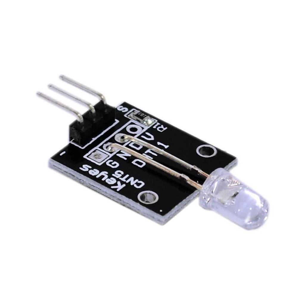
While the 7-color automatic flashing LED module appears to be a simple two-pin device from a functional standpoint, it actually has three physical pins: VCC (for power), Ground, and a third pin that is internally unconnected and thus unused for operation. This design offers flexibility in how you power the module.
There are two primary ways to power your KY-034 module:
- Direct Power Connection: You can connect the VCC pin directly to the +5V power output of your Arduino or Raspberry Pi. This provides continuous power to the module, allowing it to start flashing as soon as your board is powered on.
- Digital Pin Control: For more control over when the LED flashes, you can connect the VCC pin to an available digital (GPIO) pin on your microcontroller. This method allows you to turn the module on or off programmatically from your code, conserving power or activating the LED only when needed for specific events in your project.
Interfacing with Arduino
Controlling the KY-034 module with an Arduino is straightforward. By connecting the VCC pin to a digital output pin on your Arduino, you can toggle the LED module's power on and off. The following example demonstrates how to activate the 7-color flashing module for 20 seconds and then turn it off for another 20 seconds, repeating this cycle indefinitely. For this setup, we'll connect the module's VCC pin to Arduino's digital pin 11.
void setup() {
 // Set digital pin 11 as an output. This pin will control the power to the LED module.
 pinMode(11, OUTPUT);
}
void loop() {
 // Turn on the LED module by setting pin 11 to HIGH (providing 5V).
 digitalWrite(11, HIGH);
 // Keep the LED on for 20,000 milliseconds (20 seconds).
 delay(20000);
 // Turn off the LED module by setting pin 11 to LOW (cutting off power).
 digitalWrite(11, LOW);
 // Keep the LED off for 20,000 milliseconds (20 seconds).
 delay(20000);
}
Interfacing with Raspberry Pi
Similarly, you can integrate the KY-034 module with a Raspberry Pi using its GPIO (General Purpose Input/Output) pins. The principle remains the same: control the power to the module via a GPIO pin. For this example, we'll connect the module's VCC pin to Raspberry Pi's GPIO pin 17. Remember to set the GPIO mode to BCM (Broadcom SOC channel numbers) for consistency.
import RPi.GPIO as GPIO
import time
# Set the GPIO numbering mode to BCM.
GPIO.setmode(GPIO.BCM)
# Configure GPIO pin 17 as an output pin.
GPIO.setup(17, GPIO.OUT)
# Start an infinite loop to control the LED.
while True:
 # Turn on the LED module by setting GPIO 17 to HIGH.
 GPIO.output(17, GPIO.HIGH)
 # Pause for 1 second.
 time.sleep(1)
 # Turn off the LED module by setting GPIO 17 to LOW.
 GPIO.output(17, GPIO.LOW)
 # Pause for 1 second.
 time.sleep(1)
Applications
The KY-034 7-color flashing LED module is a fantastic component for adding visual flair and feedback to your electronic projects. Its automatic color cycling makes it perfect for:
- Status Indicators: Provide a dynamic visual cue for system status, alerts, or operation modes.
- Decorative Lighting: Enhance the aesthetics of models, robotics, or art installations.
- Educational Projects: An excellent starting point for learning about basic LED control and microcontroller interfacing.
- Ambiance Lighting: Create subtle, evolving background illumination in small spaces.