Features:
- Distance Adjustable: Detection range from 2cm to 40cm, adjustable via potentiometer.
- Wide Voltage Compatibility: Operates at 3.3V to 5V; works with Arduino, ESP32, ESP8266, Raspberry Pi, etc.
- Ambient Light Adaptability: Performs reliably under varying light conditions.
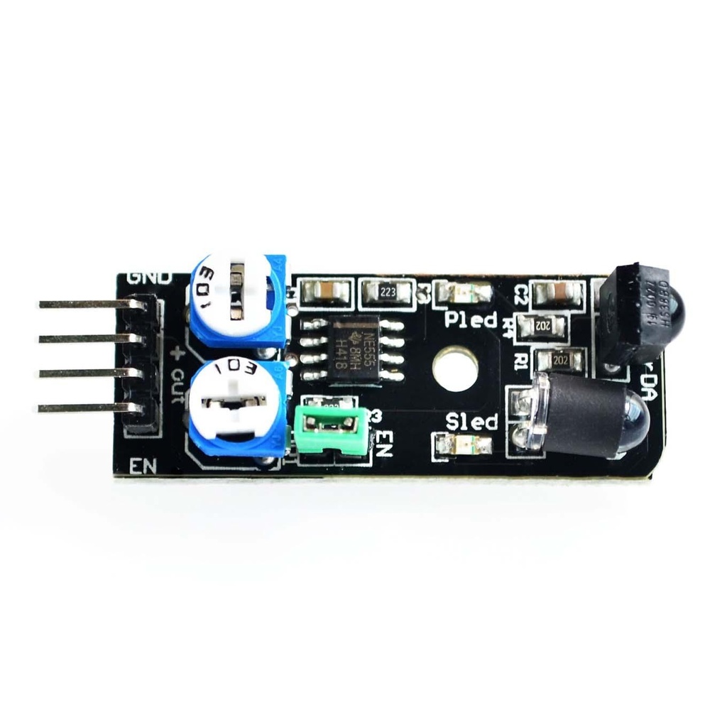
- Infrared Emitter and Receiver: Uses IR LED and photodiode for reflection-based detection.
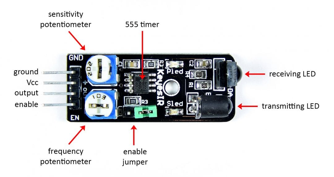
- Simple Pin Configuration: 4 pins - GND, + (Vcc), S (Signal), EN (Enable); jumper configurable.
- Distance and Frequency Adjustment: Left knob adjusts range; right knob adjusts IR pulse frequency.
- Low Power Consumption: Operates at 20mA current.
- Temperature Range: -10°C to 50°C operating environment.
- Effective Angle: 35° detection cone.
- Compact Design: 1.6 x 4 cm, weight: 9g.
- TTL Output: LOW signal = obstacle detected; HIGH = no obstacle.
- Multi-turn Resistance: Enables fine-tuning of sensitivity and range.
- IR Pulse Frequency: Operates at 38kHz, compliant with HS0038DB specs.
Principle of Work:
- IR Emission: IR LED emits 38kHz pulses outward.
- Reflection Detection: IR photoreceptor detects reflected light from objects.
- Logic Output: Output is HIGH when no object; LOW when object is detected.
Interaction with Microcontroller (MCU):
- Connections: Connect GND, Vcc, S (Signal) to MCU digital input, and EN to digital output (optional).
- Voltage Supply: 3.3V–6V DC.
- Sensitivity Adjustment: Adjust using onboard trimpots.
- Output Signal: Digital HIGH/LOW.
- Enable Pin: HIGH to enable; LOW to disable. Jumper available for always-on mode.
- Programming: Read digital pin and act accordingly (e.g., turn on LED, stop motor).
Pinout:
| Pin Name | Description | Additional Info |
|---|---|---|
| GND | Ground (0V) | Common ground reference |
| + | Vcc (3.3V–6V) | Positive power supply |
| S | Signal Output | LOW when object detected, HIGH otherwise |
| EN | Enable Pin | HIGH = enabled; LOW = disabled |
Applications:
- Obstacle avoidance in robotics
- Line-following robots
- Proximity sensing in sanitizers and faucets
- Security and intrusion detection
- Smart lighting control
- Object counting and positioning in automation
- Gesture recognition
- Automatic door opening
- Interactive displays and kiosks
- DIY electronics and automation projects
Circuit Diagram:
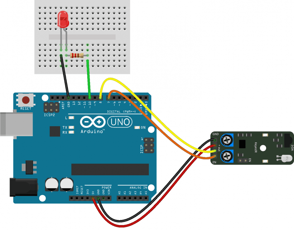
| Component | Arduino Pin | Connection |
|---|---|---|
| IR Sensor - Signal | Pin 8 | Connects to digital input |
| IR Sensor - + | 5V | Vcc power |
| IR Sensor - GND | GND | Common ground |
| IR Sensor - EN | Pin 7 | Enable control |
| LED - Anode | Pin 10 | Output indicator |
| LED - Cathode | GND | Via 220Ω resistor |
Library:
No library required.
Example Code:
int sensorPin = 8;
int enablePin = 7;
int ledPin = 10;

void setup() {
  pinMode(sensorPin, INPUT);
  pinMode(enablePin, OUTPUT);
  pinMode(ledPin, OUTPUT);
}

void loop() {
  digitalWrite(enablePin, HIGH);  // Enable sensor
  int val = digitalRead(sensorPin);

  if (val == HIGH) {
    digitalWrite(ledPin, HIGH);  // Obstacle detected
  } else {
    digitalWrite(ledPin, LOW);   // No obstacle
  }
}
Technical Details:
- Operating Voltage: 3.3V – 6V DC
- Operating Current: ≥ 20mA
- Detection Range: 2cm to 40cm
- Detection Angle: 35°
- Output: LOW (obstacle), HIGH (clear)
- Sensitivity: Adjustable via trimpot
- Temperature Range: -10°C to +50°C
- Output Signal: TTL level
Resources:
- Fritzing Part: KY-032 IR Sensor Module
- Datasheets: HS0038DB IR Receiver, NE555 Timer
Comparison Table:
| Feature | IR Obstacle Module | KY-032 Module |
|---|---|---|
| Detection Range | 2–20cm | 2–40cm |
| Detection Angle | 35° | 35° |
| Voltage | 3–5V | 3.3–6V |
| Indicator LED | Yes | Yes |
| Output | TTL | TTL |
| Adjustable Range | Yes | Yes (more precise) |
| Module Size | 3.1 x 1.5 cm | 4 x 1.6 cm |
Features:
- Distance Adjustable: Detection range from 2cm to 40cm, adjustable via potentiometer.
- Wide Voltage Compatibility: Operates at 3.3V to 5V; works with Arduino, ESP32, ESP8266, Raspberry Pi, etc.
- Ambient Light Adaptability: Performs reliably under varying light conditions.
- Infrared Emitter and Receiver: Uses IR LED and photodiode for reflection-based detection.
- Simple Pin Configuration: 4 pins - GND, + (Vcc), S (Signal), EN (Enable); jumper configurable.
- Distance and Frequency Adjustment: Left knob adjusts range; right knob adjusts IR pulse frequency.
- Low Power Consumption: Operates at 20mA current.
- Temperature Range: -10°C to 50°C operating environment.
- Effective Angle: 35° detection cone.
- Compact Design: 1.6 x 4 cm, weight: 9g.
- TTL Output: LOW signal = obstacle detected; HIGH = no obstacle.
- Multi-turn Resistance: Enables fine-tuning of sensitivity and range.
- IR Pulse Frequency: Operates at 38kHz, compliant with HS0038DB specs.
Principle of Work:
- IR Emission: IR LED emits 38kHz pulses outward.
- Reflection Detection: IR photoreceptor detects reflected light from objects.
- Logic Output: Output is HIGH when no object; LOW when object is detected.
Interaction with Microcontroller (MCU):
- Connections: Connect GND, Vcc, S (Signal) to MCU digital input, and EN to digital output (optional).
- Voltage Supply: 3.3V–6V DC.
- Sensitivity Adjustment: Adjust using onboard trimpots.
- Output Signal: Digital HIGH/LOW.
- Enable Pin: HIGH to enable; LOW to disable. Jumper available for always-on mode.
- Programming: Read digital pin and act accordingly (e.g., turn on LED, stop motor).
Pinout:
| Pin Name | Description | Additional Info |
|---|---|---|
| GND | Ground (0V) | Common ground reference |
| + | Vcc (3.3V–6V) | Positive power supply |
| S | Signal Output | LOW when object detected, HIGH otherwise |
| EN | Enable Pin | HIGH = enabled; LOW = disabled |
Applications:
- Obstacle avoidance in robotics
- Line-following robots
- Proximity sensing in sanitizers and faucets
- Security and intrusion detection
- Smart lighting control
- Object counting and positioning in automation
- Gesture recognition
- Automatic door opening
- Interactive displays and kiosks
- DIY electronics and automation projects
Circuit Diagram:
| Component | Arduino Pin | Connection |
|---|---|---|
| IR Sensor - Signal | Pin 8 | Connects to digital input |
| IR Sensor - + | 5V | Vcc power |
| IR Sensor - GND | GND | Common ground |
| IR Sensor - EN | Pin 7 | Enable control |
| LED - Anode | Pin 10 | Output indicator |
| LED - Cathode | GND | Via 220Ω resistor |
Library:
No library required.
Example Code:
int sensorPin = 8;
int enablePin = 7;
int ledPin = 10;

void setup() {
  pinMode(sensorPin, INPUT);
  pinMode(enablePin, OUTPUT);
  pinMode(ledPin, OUTPUT);
}

void loop() {
  digitalWrite(enablePin, HIGH);  // Enable sensor
  int val = digitalRead(sensorPin);

  if (val == HIGH) {
    digitalWrite(ledPin, HIGH);  // Obstacle detected
  } else {
    digitalWrite(ledPin, LOW);   // No obstacle
  }
}
Technical Details:
- Operating Voltage: 3.3V – 6V DC
- Operating Current: ≥ 20mA
- Detection Range: 2cm to 40cm
- Detection Angle: 35°
- Output: LOW (obstacle), HIGH (clear)
- Sensitivity: Adjustable via trimpot
- Temperature Range: -10°C to +50°C
- Output Signal: TTL level
Resources:
- Fritzing Part: KY-032 IR Sensor Module
- Datasheets: HS0038DB IR Receiver, NE555 Timer
Comparison Table:
| Feature | IR Obstacle Module | KY-032 Module |
|---|---|---|
| Detection Range | 2–20cm | 2–40cm |
| Detection Angle | 35° | 35° |
| Voltage | 3–5V | 3.3–6V |
| Indicator LED | Yes | Yes |
| Output | TTL | TTL |
| Adjustable Range | Yes | Yes (more precise) |
| Module Size | 3.1 x 1.5 cm | 4 x 1.6 cm |