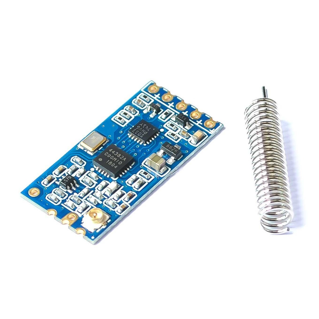
Wireless HC12 SI4463 Serial Port Transceiver Module
Features
- Long-distance transmission (up to 1000m in open space @ 5000bps)
- 100 communication channels available
- Maximum transmitting power: 100mW (20dBm), adjustable across 8 levels
- Three working modes suitable for different applications
- Built-in MCU, communication via UART
Specifications
- Supply Voltage: 3.2V to 5.5V DC
- Communication Distance: 1000m (open space)
- Serial Baud Rate: 1.2Kbps to 115.2Kbps (default: 9.6Kbps)
- Receiving Sensitivity: -117dBm to -100dBm
- Transmit Power: -1dBm to 20dBm (adjustable)
- Interface Protocol: UART/TTL
- Operating Temperature: -40℃ to +85℃
- Dimensions: 27.8mm x 14.4mm x 4mm
Applications
- Sensor Networks / Data Collection
- Wireless Metering
- Access Control / Identity Discrimination
- IT Home Appliances
- Smart Home / Security Systems
- Remote Control / Measurement Systems
- Weather Stations
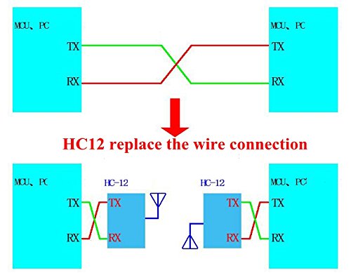
Typical Application
The HC-12 module is well-suited for wireless serial communication between microcontrollers or between a microcontroller and a PC.

Pin Definitions
- VCC: Regulated 3.3V to 5V input (min. 200mA)
- GND: Common ground with MCU
- RDX: Serial data input (connect to TX of MCU)
- TXD: Serial data output (connect to RX of MCU)
- SET: Mode selection pin (leave floating for normal mode, pull LOW for configuration mode)
Arduino Connections Example
Using two Arduino Nano boards to set up one as sender and the other as receiver with HC-12 modules.

Arduino Example Code
The provided Arduino sketch demonstrates Latch Mode, Momentary Mode (selectable via A5 pin), and feedback signaling. It includes pin mapping, serial communication setup, and toggle logic for transmitting and receiving modules. The same code can be used on both the TX and RX sides by setting A4 HIGH/LOW.
#define P1 2
#define P2 3
#define P3 4
#define P4 5
#define F1 6 // Feedback LED or Output
#define F2 7
#define F3 8
#define F4 9

#include <SoftwareSerial.h>

SoftwareSerial mySerial(10, 11); // RX, TX for HC-12

boolean p1 = false;
boolean p2 = false;
boolean p3 = false;
boolean p4 = false;

void setup() {
 Serial.begin(9600);
 mySerial.begin(9600);

 pinMode(P1, INPUT_PULLUP);
 pinMode(P2, INPUT_PULLUP);
 pinMode(P3, INPUT_PULLUP);
 pinMode(P4, INPUT_PULLUP);

 pinMode(F1, OUTPUT);
 pinMode(F2, OUTPUT);
 pinMode(F3, OUTPUT);
 pinMode(F4, OUTPUT);
}

void loop() {
 // Transmitter side
 if (digitalRead(A4) == HIGH) {
 if (digitalRead(P1) == LOW) {
 mySerial.write('A');
 delay(200);
 }
 if (digitalRead(P2) == LOW) {
 mySerial.write('B');
 delay(200);
 }
 if (digitalRead(P3) == LOW) {
 mySerial.write('C');
 delay(200);
 }
 if (digitalRead(P4) == LOW) {
 mySerial.write('D');
 delay(200);
 }
 }

 // Receiver side
 if (digitalRead(A4) == LOW) {
 if (mySerial.available()) {
 char c = mySerial.read();
 Serial.println(c); // for debugging
 if (digitalRead(A5) == LOW) {
 // Latch Mode
 if (c == 'A') {
 p1 = !p1;
 digitalWrite(F1, p1);
 }
 if (c == 'B') {
 p2 = !p2;
 digitalWrite(F2, p2);
 }
 if (c == 'C') {
 p3 = !p3;
 digitalWrite(F3, p3);
 }
 if (c == 'D') {
 p4 = !p4;
 digitalWrite(F4, p4);
 }
 } else {
 // Momentary Mode
 if (c == 'A') {
 digitalWrite(F1, HIGH);
 delay(500);
 digitalWrite(F1, LOW);
 }
 if (c == 'B') {
 digitalWrite(F2, HIGH);
 delay(500);
 digitalWrite(F2, LOW);
 }
 if (c == 'C') {
 digitalWrite(F3, HIGH);
 delay(500);
 digitalWrite(F3, LOW);
 }
 if (c == 'D') {
 digitalWrite(F4, HIGH);
 delay(500);
 digitalWrite(F4, LOW);
 }
 }
 }
 }
}
Features
- Long-distance transmission (up to 1000m in open space @ 5000bps)
- 100 communication channels available
- Maximum transmitting power: 100mW (20dBm), adjustable across 8 levels
- Three working modes suitable for different applications
- Built-in MCU, communication via UART
Specifications
- Supply Voltage: 3.2V to 5.5V DC
- Communication Distance: 1000m (open space)
- Serial Baud Rate: 1.2Kbps to 115.2Kbps (default: 9.6Kbps)
- Receiving Sensitivity: -117dBm to -100dBm
- Transmit Power: -1dBm to 20dBm (adjustable)
- Interface Protocol: UART/TTL
- Operating Temperature: -40℃ to +85℃
- Dimensions: 27.8mm x 14.4mm x 4mm
Applications
- Sensor Networks / Data Collection
- Wireless Metering
- Access Control / Identity Discrimination
- IT Home Appliances
- Smart Home / Security Systems
- Remote Control / Measurement Systems
- Weather Stations
Typical Application
The HC-12 module is well-suited for wireless serial communication between microcontrollers or between a microcontroller and a PC.
Pin Definitions
- VCC: Regulated 3.3V to 5V input (min. 200mA)
- GND: Common ground with MCU
- RDX: Serial data input (connect to TX of MCU)
- TXD: Serial data output (connect to RX of MCU)
- SET: Mode selection pin (leave floating for normal mode, pull LOW for configuration mode)
Arduino Connections Example
Using two Arduino Nano boards to set up one as sender and the other as receiver with HC-12 modules.
Arduino Example Code
The provided Arduino sketch demonstrates Latch Mode, Momentary Mode (selectable via A5 pin), and feedback signaling. It includes pin mapping, serial communication setup, and toggle logic for transmitting and receiving modules. The same code can be used on both the TX and RX sides by setting A4 HIGH/LOW.
#define P1 2
#define P2 3
#define P3 4
#define P4 5
#define F1 6 // Feedback LED or Output
#define F2 7
#define F3 8
#define F4 9

#include <SoftwareSerial.h>

SoftwareSerial mySerial(10, 11); // RX, TX for HC-12

boolean p1 = false;
boolean p2 = false;
boolean p3 = false;
boolean p4 = false;

void setup() {
 Serial.begin(9600);
 mySerial.begin(9600);

 pinMode(P1, INPUT_PULLUP);
 pinMode(P2, INPUT_PULLUP);
 pinMode(P3, INPUT_PULLUP);
 pinMode(P4, INPUT_PULLUP);

 pinMode(F1, OUTPUT);
 pinMode(F2, OUTPUT);
 pinMode(F3, OUTPUT);
 pinMode(F4, OUTPUT);
}

void loop() {
 // Transmitter side
 if (digitalRead(A4) == HIGH) {
 if (digitalRead(P1) == LOW) {
 mySerial.write('A');
 delay(200);
 }
 if (digitalRead(P2) == LOW) {
 mySerial.write('B');
 delay(200);
 }
 if (digitalRead(P3) == LOW) {
 mySerial.write('C');
 delay(200);
 }
 if (digitalRead(P4) == LOW) {
 mySerial.write('D');
 delay(200);
 }
 }

 // Receiver side
 if (digitalRead(A4) == LOW) {
 if (mySerial.available()) {
 char c = mySerial.read();
 Serial.println(c); // for debugging
 if (digitalRead(A5) == LOW) {
 // Latch Mode
 if (c == 'A') {
 p1 = !p1;
 digitalWrite(F1, p1);
 }
 if (c == 'B') {
 p2 = !p2;
 digitalWrite(F2, p2);
 }
 if (c == 'C') {
 p3 = !p3;
 digitalWrite(F3, p3);
 }
 if (c == 'D') {
 p4 = !p4;
 digitalWrite(F4, p4);
 }
 } else {
 // Momentary Mode
 if (c == 'A') {
 digitalWrite(F1, HIGH);
 delay(500);
 digitalWrite(F1, LOW);
 }
 if (c == 'B') {
 digitalWrite(F2, HIGH);
 delay(500);
 digitalWrite(F2, LOW);
 }
 if (c == 'C') {
 digitalWrite(F3, HIGH);
 delay(500);
 digitalWrite(F3, LOW);
 }
 if (c == 'D') {
 digitalWrite(F4, HIGH);
 delay(500);
 digitalWrite(F4, LOW);
 }
 }
 }
 }
}