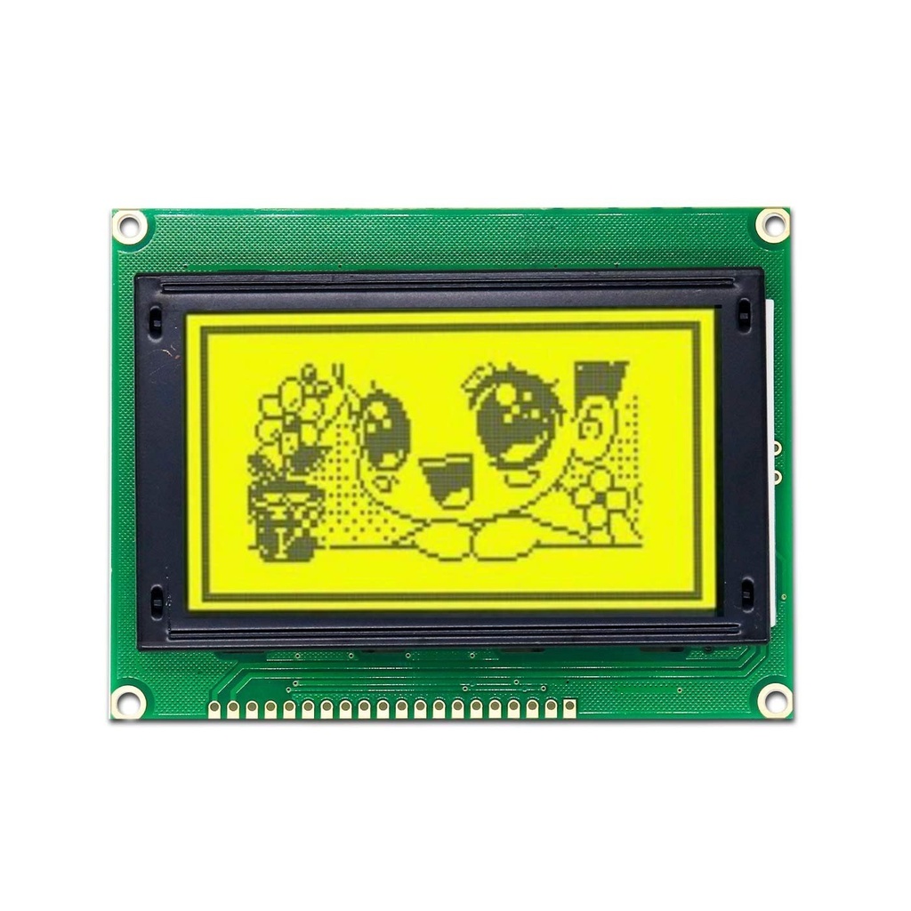
LCD 128x64 Graphical Display Yellow Background
The 12864B Graphic LCD module is a 128 x 64 pixel display featuring a yellow backlight and white text/graphics. It supports both text and graphical output and can operate in either parallel or serial (SPI) mode. When configured for SPI mode, only three data pins are needed, making it ideal for microcontroller projects with limited I/O. The contrast is pre-set by the factory, eliminating the need for external potentiometers.
Package Includes:
- 1 x 12864B Graphic LCD Display Module
Specifications:
- Encapsulation: COB (Chip-on-Board)
- Display Format: 128x64 dots
- Display Type: STN, Transflective, Positive
- Backlight Color: Yellow
- Controller: ST7920
- Interface: 8-bit parallel or SPI serial mode
- Driving Scheme: 1/64 Duty Cycle, 1/9 Bias
- Power Supply Voltage: 5.0 V
- Operating Temperature: -20°C to +70°C
- Storage Temperature: -30°C to +80°C
PSB Configuration (Interface Selection):

The LCD is shipped with the PSB pin (parallel/serial mode select) shorted to VDD by a 0-ohm resistor at R9, which sets it to parallel mode. To switch to SPI mode:
- Move the resistor to R10, or
- Remove the resistor entirely and connect the PSB pin to GND
Arduino Connections in Serial (SPI) Mode
For Arduino Uno:
| LCD Pin | Arduino UNO |
|---|---|
| K (Backlight Cathode) | GND |
| A (Backlight Anode) | +5V |
| PSD (SPI Mode) | GND |
| E (SCK) | D13 |
| R/W (MOSI) | D11 |
| RS (CS) | D10 * |
| VDD | +5V |
| VSS | GND |
For Arduino Mega:
| LCD Pin | Arduino Mega |
|---|---|
| K (Backlight Cathode) | GND |
| A (Backlight Anode) | +5V |
| PSD (SPI Mode) | GND |
| E (SCK) | D52 |
| R/W (MOSI) | D51 |
| RS (CS) | D53 * |
| VDD | +5V |
| VSS | GND |
*RS/CS pin is defined in software using #define CS_PIN 10
Recommended Library:
We recommend the U8glib library for this display. You can download it here:
Example Arduino Code (SPI Mode):
#include "U8glib.h"

#define CS_PIN 10

U8GLIB_ST7920_128X64_1X u8g(CS_PIN);

void setup() {
  // No setup required for this example
}

void loop() {
  u8g.firstPage();
  do {
    u8g.setFont(u8g_font_courB14);
    u8g.drawStr(35, 26, "HOBBY");
    u8g.drawStr(8, 46, "COMPONENTS");
    u8g.drawFrame(5, 5, 117, 54);
    u8g.drawFrame(3, 3, 121, 58);
  } while (u8g.nextPage());
}
Specifications:
- Encapsulation: COB (Chip-on-Board)
- Display Format: 128x64 dots
- Display Type: STN, Transflective, Positive
- Backlight Color: Yellow
- Controller: ST7920
- Interface: 8-bit parallel or SPI serial mode
- Driving Scheme: 1/64 Duty Cycle, 1/9 Bias
- Power Supply Voltage: 5.0 V
- Operating Temperature: -20°C to +70°C
- Storage Temperature: -30°C to +80°C
PSB Configuration (Interface Selection):
The LCD is shipped with the PSB pin (parallel/serial mode select) shorted to VDD by a 0-ohm resistor at R9, which sets it to parallel mode. To switch to SPI mode:
- Move the resistor to R10, or
- Remove the resistor entirely and connect the PSB pin to GND
Arduino Connections in Serial (SPI) Mode
For Arduino Uno:
| LCD Pin | Arduino UNO |
|---|---|
| K (Backlight Cathode) | GND |
| A (Backlight Anode) | +5V |
| PSD (SPI Mode) | GND |
| E (SCK) | D13 |
| R/W (MOSI) | D11 |
| RS (CS) | D10 * |
| VDD | +5V |
| VSS | GND |
For Arduino Mega:
| LCD Pin | Arduino Mega |
|---|---|
| K (Backlight Cathode) | GND |
| A (Backlight Anode) | +5V |
| PSD (SPI Mode) | GND |
| E (SCK) | D52 |
| R/W (MOSI) | D51 |
| RS (CS) | D53 * |
| VDD | +5V |
| VSS | GND |
*RS/CS pin is defined in software using #define CS_PIN 10
Recommended Library:
We recommend the U8glib library for this display. You can download it here:
Example Arduino Code (SPI Mode):
#include "U8glib.h"

#define CS_PIN 10

U8GLIB_ST7920_128X64_1X u8g(CS_PIN);

void setup() {
  // No setup required for this example
}

void loop() {
  u8g.firstPage();
  do {
    u8g.setFont(u8g_font_courB14);
    u8g.drawStr(35, 26, "HOBBY");
    u8g.drawStr(8, 46, "COMPONENTS");
    u8g.drawFrame(5, 5, 117, 54);
    u8g.drawFrame(3, 3, 121, 58);
  } while (u8g.nextPage());
}