Specifications:
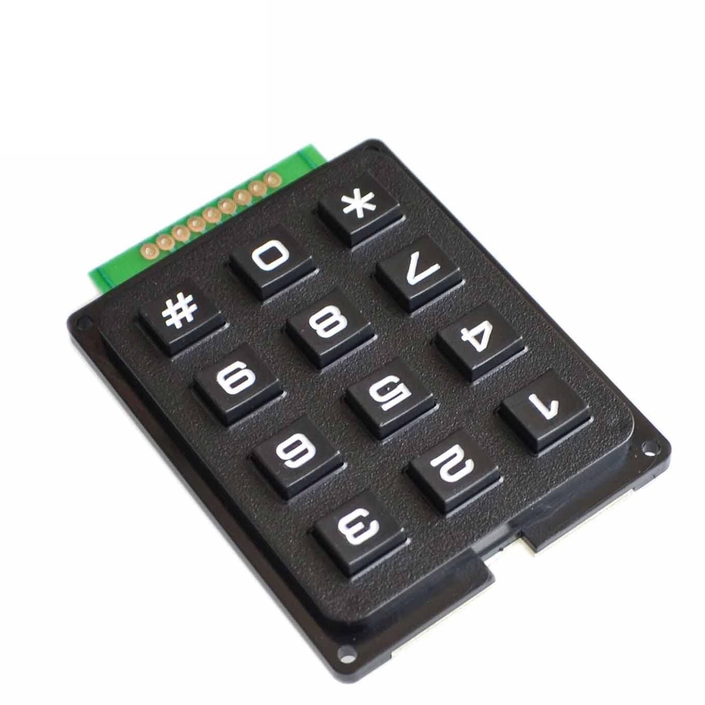
| Number of keys |
12 |
| Mechanical durability |
1,000,000 cycles |
| Max. contact resistance |
200 mΩ |
| Material |
Plastic |
| Max. operating voltage |
24V DC |
| Switching torque |
1N |
| Keystroke |
1.2mm |
| Max. operating current |
20mA |
| Width |
51mm |
| Height |
64mm |
| Operating temperature |
-20 to 60°C |
| Keypad color |
Black |
| Keypad type |
Numeric |
Wiring with Arduino:
The keypad can be used with an Arduino Uno-compatible board and an I2C LCD for output. If an LCD is not available, the serial monitor can be used instead.
- Keypad Row 1 → Arduino digital pin 5
- Keypad Row 2 → Arduino digital pin 4
- Keypad Row 3 → Arduino digital pin 3
- Keypad Row 4 → Arduino digital pin 2
- Keypad Column 1 → Arduino digital pin 8
- Keypad Column 2 → Arduino digital pin 7
- Keypad Column 3 → Arduino digital pin 6
If your keypad layout differs, modify the rowPins[ROWS] and colPins[COLS] arrays accordingly in the code.
Arduino Code:
#include <Keypad.h>

const byte ROWS = 4; // four rows
const byte COLS = 3; // three columns

char keys[ROWS][COLS] = {
  {'1','2','3'},
  {'4','5','6'},
  {'7','8','9'},
  {'*','0','#'}
};

byte rowPins[ROWS] = {9, 8, 7, 6}; // connect to the row pinouts
byte colPins[COLS] = {5, 4, 3};    // connect to the column pinouts

Keypad keypad = Keypad(makeKeymap(keys), rowPins, colPins, ROWS, COLS);

void setup() {
  Serial.begin(9600);
}

void loop() {
  char key = keypad.getKey();
  if (key) {
    Serial.print("Key Pressed : ");
    Serial.println(key);
  }
}
Specifications:
| Number of keys |
12 |
| Mechanical durability |
1,000,000 cycles |
| Max. contact resistance |
200 mΩ |
| Material |
Plastic |
| Max. operating voltage |
24V DC |
| Switching torque |
1N |
| Keystroke |
1.2mm |
| Max. operating current |
20mA |
| Width |
51mm |
| Height |
64mm |
| Operating temperature |
-20 to 60°C |
| Keypad color |
Black |
| Keypad type |
Numeric |
Wiring with Arduino:
The keypad can be used with an Arduino Uno-compatible board and an I2C LCD for output. If an LCD is not available, the serial monitor can be used instead.
- Keypad Row 1 → Arduino digital pin 5
- Keypad Row 2 → Arduino digital pin 4
- Keypad Row 3 → Arduino digital pin 3
- Keypad Row 4 → Arduino digital pin 2
- Keypad Column 1 → Arduino digital pin 8
- Keypad Column 2 → Arduino digital pin 7
- Keypad Column 3 → Arduino digital pin 6
If your keypad layout differs, modify the rowPins[ROWS] and colPins[COLS] arrays accordingly in the code.
Arduino Code:
#include <Keypad.h>

const byte ROWS = 4; // four rows
const byte COLS = 3; // three columns

char keys[ROWS][COLS] = {
  {'1','2','3'},
  {'4','5','6'},
  {'7','8','9'},
  {'*','0','#'}
};

byte rowPins[ROWS] = {9, 8, 7, 6}; // connect to the row pinouts
byte colPins[COLS] = {5, 4, 3};    // connect to the column pinouts

Keypad keypad = Keypad(makeKeymap(keys), rowPins, colPins, ROWS, COLS);

void setup() {
  Serial.begin(9600);
}

void loop() {
  char key = keypad.getKey();
  if (key) {
    Serial.print("Key Pressed : ");
    Serial.println(key);
  }
}