Features:
- Two selectable differential input channels
- On-chip low noise PGA with selectable gain (32, 64, 128)
- On-chip power supply regulator for load cell and ADC analog supply
- Built-in oscillator (optional external crystal supported)
- Power-on-reset and low power standby
- No programming required – simple pin-driven control
- Selectable output data rate: 10SPS or 80SPS
- Simultaneous 50Hz and 60Hz rejection
Specifications:
- HX711:
- Operating Voltage: 2.7 - 5VDC
- Differential Input Voltage: ±40mV
- Data Accuracy: 24-bit
- Refresh Frequency: 10Hz / 80Hz
- Operating Current: < 1.5 mA
- Standby Current: < 1 uA
- Dimensions: 24 x 16mm
- 20Kg Load Sensor:
- Capacity: 10 - 20 Kg
- Input/Output Resistance: 1000 ± 20 Ω
- Insulation Resistance: ≥5000 MΩ
- Excitation Voltage: ≤10V
- Operating Temp: 0 – 50°C
- Overload Capacity: 150% F.S
- Dimensions: 80 x 12.7 x 12.7mm
Applications:
- Kitchen scales
- Industrial and postal weighing systems
- Luggage weighing and DIY smart weight projects
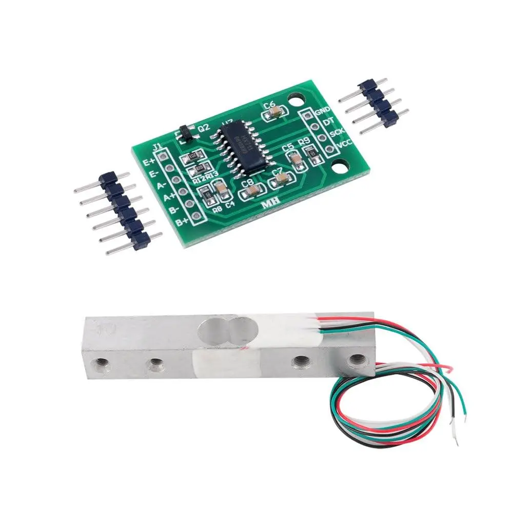
Pin Connections:
Weight Sensor:
| Wire Color | Connection |
|---|---|
| Red | E+ |
| Black | E- |
| Green | A+ |
| White | A- |
HX711 Module:

Sample Project:
Circuit Diagram:

Libraries:
Calibration Sketch:
#include "HX711.h"

#define LOADCELL_DOUT_PIN 3
#define LOADCELL_SCK_PIN 2

HX711 scale;
float calibration_factor = -7050; // Change as needed

void setup() {
  Serial.begin(9600);
  Serial.println("HX711 calibration sketch");
  scale.begin(LOADCELL_DOUT_PIN, LOADCELL_SCK_PIN);
  scale.set_scale();
  scale.tare();
  long zero_factor = scale.read_average();
  Serial.print("Zero factor: ");
  Serial.println(zero_factor);
}

void loop() {
  scale.set_scale(calibration_factor);
  Serial.print("Reading: ");
  Serial.print(scale.get_units(), 1);
  Serial.print(" lbs    Calibration Factor: ");
  Serial.println(calibration_factor);

  if (Serial.available()) {
    char temp = Serial.read();
    if (temp == '+' || temp == 'a') calibration_factor += 10;
    else if (temp == '-' || temp == 'z') calibration_factor -= 10;
  }
}
Example Program:
#include "HX711.h"

#define calibration_factor -7050.0
#define LOADCELL_DOUT_PIN 3
#define LOADCELL_SCK_PIN 2

HX711 scale;

void setup() {
  Serial.begin(9600);
  Serial.println("HX711 scale demo");
  scale.begin(LOADCELL_DOUT_PIN, LOADCELL_SCK_PIN);
  scale.set_scale(calibration_factor);
  scale.tare();
}

void loop() {
  Serial.print("Reading: ");
  Serial.print(scale.get_units(), 1);
  Serial.println(" lbs");
}
References:
Features:
- Two selectable differential input channels
- On-chip low noise PGA with selectable gain (32, 64, 128)
- On-chip power supply regulator for load cell and ADC analog supply
- Built-in oscillator (optional external crystal supported)
- Power-on-reset and low power standby
- No programming required – simple pin-driven control
- Selectable output data rate: 10SPS or 80SPS
- Simultaneous 50Hz and 60Hz rejection
Specifications:
- HX711:
- Operating Voltage: 2.7 - 5VDC
- Differential Input Voltage: ±40mV
- Data Accuracy: 24-bit
- Refresh Frequency: 10Hz / 80Hz
- Operating Current: < 1.5 mA
- Standby Current: < 1 uA
- Dimensions: 24 x 16mm
- 20Kg Load Sensor:
- Capacity: 10 - 20 Kg
- Input/Output Resistance: 1000 ± 20 Ω
- Insulation Resistance: ≥5000 MΩ
- Excitation Voltage: ≤10V
- Operating Temp: 0 – 50°C
- Overload Capacity: 150% F.S
- Dimensions: 80 x 12.7 x 12.7mm
Applications:
- Kitchen scales
- Industrial and postal weighing systems
- Luggage weighing and DIY smart weight projects
Pin Connections:
Weight Sensor:
| Wire Color | Connection |
|---|---|
| Red | E+ |
| Black | E- |
| Green | A+ |
| White | A- |
HX711 Module:
Sample Project:
Circuit Diagram:
Libraries:
Calibration Sketch:
#include "HX711.h"

#define LOADCELL_DOUT_PIN 3
#define LOADCELL_SCK_PIN 2

HX711 scale;
float calibration_factor = -7050; // Change as needed

void setup() {
  Serial.begin(9600);
  Serial.println("HX711 calibration sketch");
  scale.begin(LOADCELL_DOUT_PIN, LOADCELL_SCK_PIN);
  scale.set_scale();
  scale.tare();
  long zero_factor = scale.read_average();
  Serial.print("Zero factor: ");
  Serial.println(zero_factor);
}

void loop() {
  scale.set_scale(calibration_factor);
  Serial.print("Reading: ");
  Serial.print(scale.get_units(), 1);
  Serial.print(" lbs    Calibration Factor: ");
  Serial.println(calibration_factor);

  if (Serial.available()) {
    char temp = Serial.read();
    if (temp == '+' || temp == 'a') calibration_factor += 10;
    else if (temp == '-' || temp == 'z') calibration_factor -= 10;
  }
}
Example Program:
#include "HX711.h"

#define calibration_factor -7050.0
#define LOADCELL_DOUT_PIN 3
#define LOADCELL_SCK_PIN 2

HX711 scale;

void setup() {
  Serial.begin(9600);
  Serial.println("HX711 scale demo");
  scale.begin(LOADCELL_DOUT_PIN, LOADCELL_SCK_PIN);
  scale.set_scale(calibration_factor);
  scale.tare();
}

void loop() {
  Serial.print("Reading: ");
  Serial.print(scale.get_units(), 1);
  Serial.println(" lbs");
}