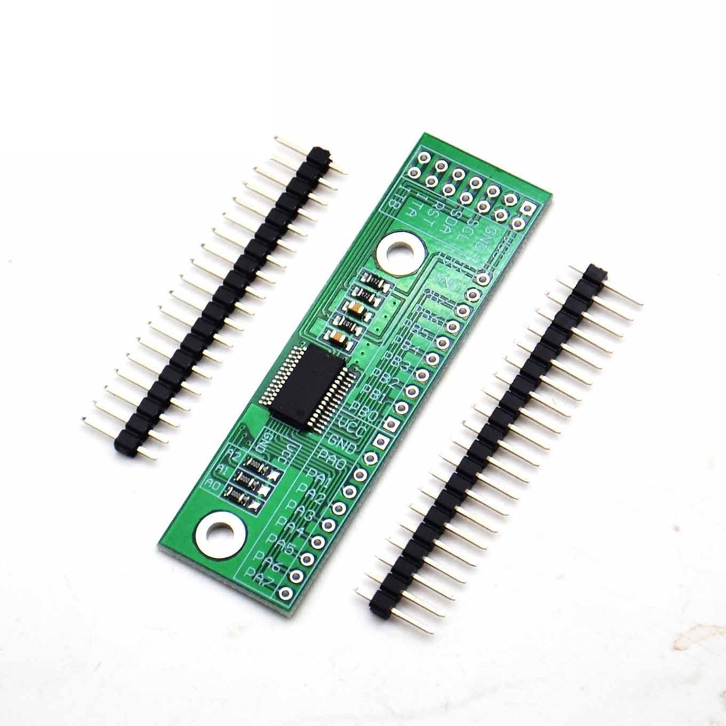
Expansion I/O Module MCP23017 I2C 16bit
An Expansion I/O Module MCP23017 I2C 16-bit is a module that expands the input/output (I/O) capabilities of a device using the MCP23017 chip and the I2C (Inter-Integrated Circuit) communication protocol. It provides 16 general-purpose I/O pins that can be configured as either inputs or outputs. These pins can be used to connect and control various devices and peripherals, such as sensors, switches, LEDs, and actuators.
Take your project to the next level with our 16 Way IO Extension Module, equipped with the powerful MCP23017 chip. Unlock new possibilities, streamline your IO management, and enjoy reliable operation every step of the way. Elevate your project's performance and efficiency with this exceptional module today.
Package Includes:
- 1x Expansion I/O Module MCP23017 I2C 16-bit
Features:
- MCP23017 Chip: The module utilizes the MCP23017 integrated circuit, manufactured by Microchip, which provides 16 general-purpose I/O pins.
- I2C Communication: The module uses the I2C protocol for communication, allowing for easy integration and control with devices supporting I2C.
- 16-Bit I/O Expansion: Offers 16 individual I/O pins configurable as inputs or outputs, providing expanded I/O capabilities for external components.
- Configurable I/O Settings: Each I/O pin can be independently configured as input or output based on project requirements.
- Pull-Up Resistors: Supports enabling pull-up resistors on I/O pins to ensure stable and reliable input readings.
- Interrupt Functionality: Includes interrupt capability for input pins to allow efficient event monitoring and response.
- High-Speed I2C Interface: Supports 100KHz, 400KHz, and 1.7MHz I2C frequencies for fast data transfer.
- Multiple Address Configurations: Three address pins allow eight different addresses, enabling up to eight modules on one I2C bus.
- Strong Driving Capacity: I/O interface can drive devices requiring up to 25mA current.
- Parallel Connection Capability: Enables connecting multiple modules in parallel to expand up to 128 I/O extensions.
Description:
The Expansion I/O Module MCP23017 I2C 16-bit is a powerful and versatile solution designed to expand the I/O capabilities of your device. Equipped with the highly regarded MCP23017 chip from Microchip, this module offers extensive features and flexibility.
With 16 individual I/O pins, independently configurable as inputs or outputs, you can connect sensors, switches, LEDs, or other peripherals. Pull-up resistors ensure stable input readings, while interrupt functionality allows rapid response to input changes.
Communication is via I2C, supporting multiple speeds and up to eight modules per bus. Parallel connections expand scalability to 128 I/O extensions. The module's strong driving capacity supports higher power devices without additional circuitry.
Ideal for automation, robotics, IoT, and more, this module is a feature-packed, flexible solution to elevate your projects.
Principle of Work:
The MCP23017 chip contains two 8-bit ports (Port A and Port B), each with eight I/O pins. The module communicates with a host device via the I2C bus using SDA (Serial Data) and SCL (Serial Clock) lines.
The host sends commands and data over I2C to configure pins as inputs or outputs, enable pull-up resistors, and set up interrupts for input pins. Address pins allow multiple modules on the same bus, each with a unique address.
Interrupt signals from input pins can trigger host actions immediately, streamlining data processing.
Pinout of the Sensor:

Key Pin Functions:
- I/O Configuration: Pins configurable as input or output for sensors, switches, LEDs, etc.
- Pull-up Resistors: Built-in resistors can be enabled on input pins for signal stability.
- Interrupt Functionality: Input pins can generate interrupts for quick host response.
- I2C Interface: Communicates via SDA and SCL lines for serial data transfer.
Module Pinout Table:
| No. | Pin | Function | Description |
|---|---|---|---|
| 1 | VCC | Power Source Input | Accepts power input 3.0V-5.5V |
| 2 | GND | Power Negative Electrode | Connected to ground (0V) |
| 3 | SCL | I2C Clock Line | Connects to MCU's I2C SCL pin for clock sync |
| 4 | SDA | I2C Data Line | Connects to MCU's I2C SDA pin for data transfer |
| 5 | RST | Chip Reset | Low-level reset signal, connect to MCU IO or leave unconnected |
| 6 | ITA | GPIOA Port Interrupt Output | Connects to MCU IO to receive interrupts from GPIOA |
| 7 | ITB | GPIOB Port Interrupt Output | Connects to MCU IO to receive interrupts from GPIOB |
Side Pins:
| Pin Name | Description |
|---|---|
| VCC | Power supply for the module - 5V |
| GND | Ground connection |
| Port B Pins | 8 pins for I/O operations (PB0-7) |
| VCC | Power supply for the module - 5V |
| Port A Pins | 8 pins for I/O operations (PA0-7) |
Applications:
- Home Automation: Connect and control smart home devices.
- Robotics: Interface with sensors, motors, and peripherals.
- Internet of Things (IoT): Expand device I/O capabilities.
- Industrial Automation: Control and monitor industrial equipment.
- Environmental Monitoring: Interface with temperature, humidity, air quality sensors.
- Home Security Systems: Connect sensors, cameras, alarms.
- Data Logging: Collect and analyze sensor data over time.
- Display Control: Drive display panels or screens.
- Custom Control Panels: Create DIY or hobbyist control setups.
- Educational Projects: Learn I2C communication and I/O expansion.
Circuit:

Library Installation:
- Download and install the Arduino IDE from Arduino official website.
- Open Arduino IDE.
- Go to Sketch > Include Library > Manage Libraries.
- Search for
Adafruit_MCP23017in the Library Manager. - Select the library and click Install.
- Wait for the installation to finish.
- Close the Library Manager.
Sample Arduino Code:
// Include the MCP23017 library
#include <Wire.h>
#include <Adafruit_MCP23017.h>

Adafruit_MCP23017 mcp;

void setup() {
  Serial.begin(9600);
  mcp.begin();      // use default address 0

  // Set pin 0 of port A as output
  mcp.pinMode(0, OUTPUT);
  // Set pin 1 of port A as input with pull-up resistor enabled
  mcp.pinMode(1, INPUT);
  mcp.pullUp(1, HIGH);
}

void loop() {
  // Turn on LED connected to pin 0 of MCP23017
  mcp.digitalWrite(0, HIGH);
  delay(1000);

  // Turn off LED
  mcp.digitalWrite(0, LOW);
  delay(1000);

  // Read button status from pin 1
  int buttonState = mcp.digitalRead(1);
  Serial.print("Button state: ");
  Serial.println(buttonState);
}
Additional Notes:
- The module operates with a voltage range of 3.0V to 5.5V, compatible with most microcontrollers.
- Use proper pull-up resistors on SDA and SCL lines if your I2C bus requires them.
- Check the module's address pins (A0, A1, A2) to set the correct I2C address if multiple modules are used.
- Use the interrupt pins ITA and ITB to handle asynchronous events efficiently.
Features:
- MCP23017 Chip: The module utilizes the MCP23017 integrated circuit, manufactured by Microchip, which provides 16 general-purpose I/O pins.
- I2C Communication: The module uses the I2C protocol for communication, allowing for easy integration and control with devices supporting I2C.
- 16-Bit I/O Expansion: Offers 16 individual I/O pins configurable as inputs or outputs, providing expanded I/O capabilities for external components.
- Configurable I/O Settings: Each I/O pin can be independently configured as input or output based on project requirements.
- Pull-Up Resistors: Supports enabling pull-up resistors on I/O pins to ensure stable and reliable input readings.
- Interrupt Functionality: Includes interrupt capability for input pins to allow efficient event monitoring and response.
- High-Speed I2C Interface: Supports 100KHz, 400KHz, and 1.7MHz I2C frequencies for fast data transfer.
- Multiple Address Configurations: Three address pins allow eight different addresses, enabling up to eight modules on one I2C bus.
- Strong Driving Capacity: I/O interface can drive devices requiring up to 25mA current.
- Parallel Connection Capability: Enables connecting multiple modules in parallel to expand up to 128 I/O extensions.
Description:
The Expansion I/O Module MCP23017 I2C 16-bit is a powerful and versatile solution designed to expand the I/O capabilities of your device. Equipped with the highly regarded MCP23017 chip from Microchip, this module offers extensive features and flexibility.
With 16 individual I/O pins, independently configurable as inputs or outputs, you can connect sensors, switches, LEDs, or other peripherals. Pull-up resistors ensure stable input readings, while interrupt functionality allows rapid response to input changes.
Communication is via I2C, supporting multiple speeds and up to eight modules per bus. Parallel connections expand scalability to 128 I/O extensions. The module's strong driving capacity supports higher power devices without additional circuitry.
Ideal for automation, robotics, IoT, and more, this module is a feature-packed, flexible solution to elevate your projects.
Principle of Work:
The MCP23017 chip contains two 8-bit ports (Port A and Port B), each with eight I/O pins. The module communicates with a host device via the I2C bus using SDA (Serial Data) and SCL (Serial Clock) lines.
The host sends commands and data over I2C to configure pins as inputs or outputs, enable pull-up resistors, and set up interrupts for input pins. Address pins allow multiple modules on the same bus, each with a unique address.
Interrupt signals from input pins can trigger host actions immediately, streamlining data processing.
Pinout of the Sensor:
Key Pin Functions:
- I/O Configuration: Pins configurable as input or output for sensors, switches, LEDs, etc.
- Pull-up Resistors: Built-in resistors can be enabled on input pins for signal stability.
- Interrupt Functionality: Input pins can generate interrupts for quick host response.
- I2C Interface: Communicates via SDA and SCL lines for serial data transfer.
Module Pinout Table:
| No. | Pin | Function | Description |
|---|---|---|---|
| 1 | VCC | Power Source Input | Accepts power input 3.0V-5.5V |
| 2 | GND | Power Negative Electrode | Connected to ground (0V) |
| 3 | SCL | I2C Clock Line | Connects to MCU's I2C SCL pin for clock sync |
| 4 | SDA | I2C Data Line | Connects to MCU's I2C SDA pin for data transfer |
| 5 | RST | Chip Reset | Low-level reset signal, connect to MCU IO or leave unconnected |
| 6 | ITA | GPIOA Port Interrupt Output | Connects to MCU IO to receive interrupts from GPIOA |
| 7 | ITB | GPIOB Port Interrupt Output | Connects to MCU IO to receive interrupts from GPIOB |
Side Pins:
| Pin Name | Description |
|---|---|
| VCC | Power supply for the module - 5V |
| GND | Ground connection |
| Port B Pins | 8 pins for I/O operations (PB0-7) |
| VCC | Power supply for the module - 5V |
| Port A Pins | 8 pins for I/O operations (PA0-7) |
Applications:
- Home Automation: Connect and control smart home devices.
- Robotics: Interface with sensors, motors, and peripherals.
- Internet of Things (IoT): Expand device I/O capabilities.
- Industrial Automation: Control and monitor industrial equipment.
- Environmental Monitoring: Interface with temperature, humidity, air quality sensors.
- Home Security Systems: Connect sensors, cameras, alarms.
- Data Logging: Collect and analyze sensor data over time.
- Display Control: Drive display panels or screens.
- Custom Control Panels: Create DIY or hobbyist control setups.
- Educational Projects: Learn I2C communication and I/O expansion.
Circuit:
Library Installation:
- Download and install the Arduino IDE from Arduino official website.
- Open Arduino IDE.
- Go to Sketch > Include Library > Manage Libraries.
- Search for
Adafruit_MCP23017in the Library Manager. - Select the library and click Install.
- Wait for the installation to finish.
- Close the Library Manager.
Sample Arduino Code:
// Include the MCP23017 library
#include <Wire.h>
#include <Adafruit_MCP23017.h>

Adafruit_MCP23017 mcp;

void setup() {
  Serial.begin(9600);
  mcp.begin();      // use default address 0

  // Set pin 0 of port A as output
  mcp.pinMode(0, OUTPUT);
  // Set pin 1 of port A as input with pull-up resistor enabled
  mcp.pinMode(1, INPUT);
  mcp.pullUp(1, HIGH);
}

void loop() {
  // Turn on LED connected to pin 0 of MCP23017
  mcp.digitalWrite(0, HIGH);
  delay(1000);

  // Turn off LED
  mcp.digitalWrite(0, LOW);
  delay(1000);

  // Read button status from pin 1
  int buttonState = mcp.digitalRead(1);
  Serial.print("Button state: ");
  Serial.println(buttonState);
}
Additional Notes:
- The module operates with a voltage range of 3.0V to 5.5V, compatible with most microcontrollers.
- Use proper pull-up resistors on SDA and SCL lines if your I2C bus requires them.
- Check the module's address pins (A0, A1, A2) to set the correct I2C address if multiple modules are used.
- Use the interrupt pins ITA and ITB to handle asynchronous events efficiently.