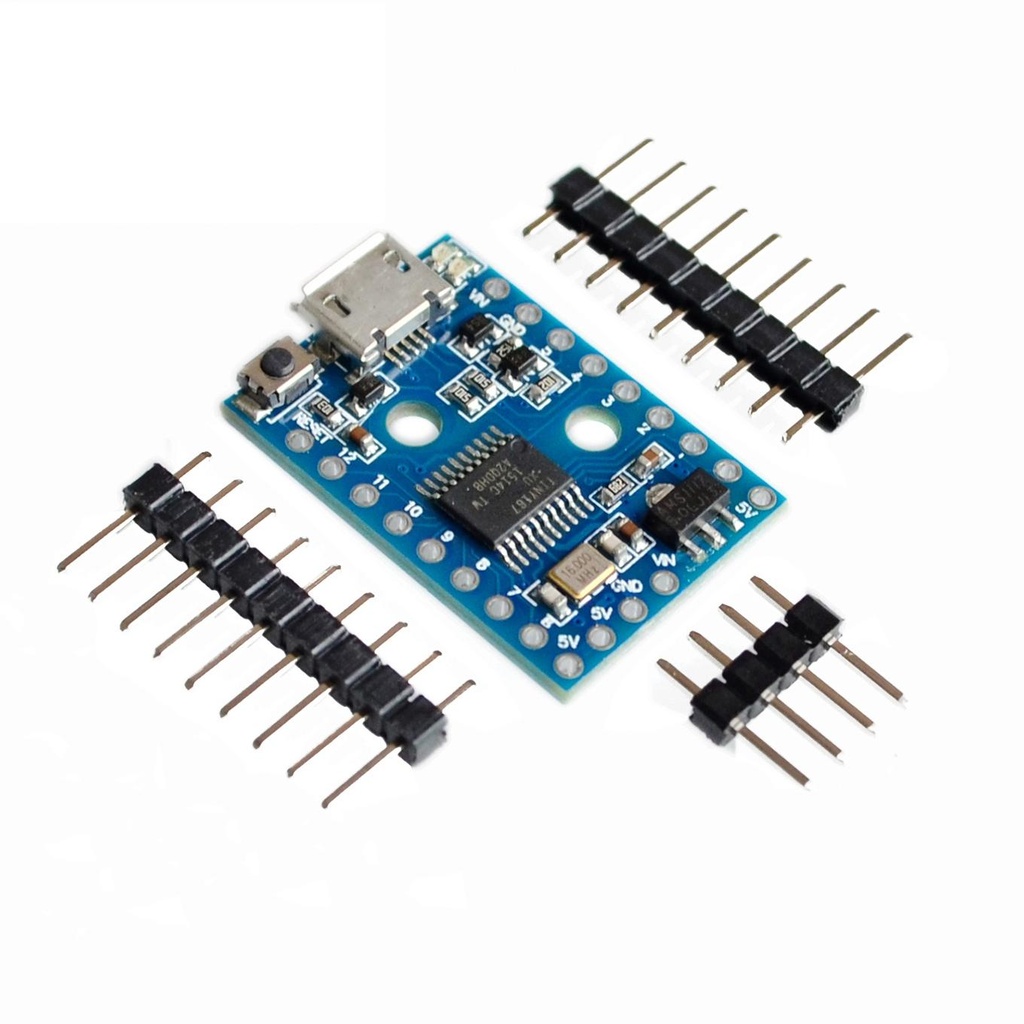
Digispark Attiny167 Development Board (Pro Compatible)
The Digispark ATTINY167 is an advanced, compatible clone of the Digispark Pro. It mirrors its counterpart's performance and pinout while offering:
- 13 versatile digital pins (11 supporting ADC, I2C, and SPI).
- Native USB functionality built directly into the chip.
- Integrated UART on pins 6 and 7 (a commonly missing feature in many Digispark boards).
- Capable of acting as a USB HID (keyboard, mouse, etc.).
Package Includes
- 1× Digispark ATTINY167 Development Board (Pro Compatible)
Features
-
Compatibility: Works with Arduino IDE 1.5+ on OSX, Windows, and Linux.
-
Easy Installation: Fully signed drivers and executable installer.
-
USB Support:
-
USB programming
-
USB device emulation
-
USB-CDC virtual serial port emulation
-
-
Clock: 16 MHz precision crystal oscillator.
-
Memory: 16KB Flash (approx. 14.5KB available after bootloader).
-
Serial Communication: USB-based communication for debugging and data transfer.
-
I/O Pins: 14 total, including 2 shared with USB.
-
Interfaces:
-
I2C
-
SPI
-
UART
-
LIN
-
USI
-
-
ADC: 10 pins support analog-to-digital conversion.
-
PWM: 3 assignable PWM channels.
-
Power Supply:
-
USB or external (5V or 6–16V input)
-
150mA 5V built-in regulator
-
-
Reset/User Button: Can be repurposed as an I/O pin.
-
LEDs:
-
Power LED
-
Test/Status LED (Pin 1)
-
-
Power Management: Solder jumpers to disable power-hungry features.
-
Mounting: Two mounting holes for secure installation.
-
Breadboard Friendly: Compact design with appropriate spacing (three side header pins for legacy shield support).
Description
This Micro USB-enabled development board is fully Arduino-compatible (ATTiny167) and eliminates the need for a USB-to-Serial converter. With 14 digital I/O and 10 analog ADCs, it supports:
-
Digispark shield ecosystem (25+ shields)
-
Enhanced pinout
-
Expanded memory
-
Native USB
-
Additional features like Wi-Fi and Bluetooth compatibility
Principle of Work
-
Microcontroller (MCU): Based on ATTiny167, containing CPU, memory, and I/O interfaces.
-
Open Hardware: Public design encourages compatibility and custom implementations.
-
Arduino-Compatible: Works seamlessly with Arduino libraries and tools.
-
Micro USB: Direct computer connection without extra hardware.
-
Bootloader & V-BUS Library: Manages USB communication and code uploading.
-
Arduino IDE: Used for programming, compiling, and uploading code.
-
Programming Workflow: Write, compile, and upload via USB. Bootloader handles it.
-
Libraries: Rich ecosystem of pre-built libraries simplifies development.
-
Hardware Control: Fully programmable I/O, ADC, PWM, and communication interfaces.
-
Community Support: Active user community for project sharing and development.
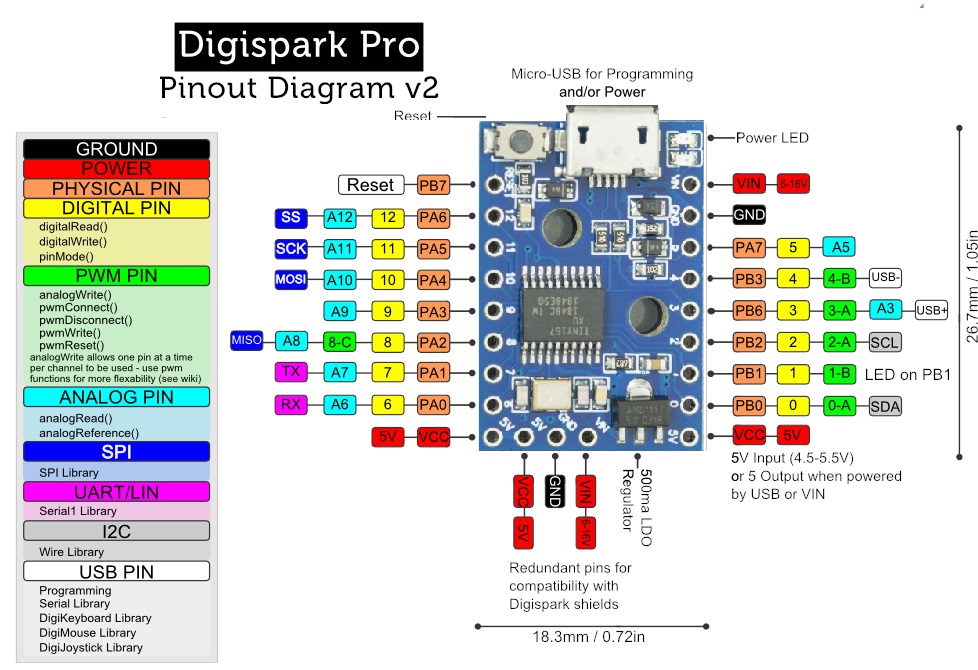
Pinout
-
5V Pin: Regulated power output for peripherals.
-
GND Pins: Common ground reference.
-
Digital I/O (0–12): Configurable as inputs or outputs.
-
PWM Outputs: 6 pins support PWM signal generation.
-
AREF Pin: Sets reference voltage (0–5V) for analog inputs.
-
I2C:
-
SDA (Serial Data)
-
SCL (Serial Clock)
-
-
UART:
-
Pins 6 and 7 (RX/TX)
-
-
USB: Micro USB for power and programming (software USB enabled).
-
Onboard LED: Connected to Pin 1.
-
Analog Inputs (A0–A7): 8 ADC input pins.
-
VIN: External power input (7–12V DC).
-
Power LED: Indicates board is powered.
Applications
-
Industrial Machinery Control
-
Solar System Management
-
IoT Projects
-
Battery Charging & Power Supply Systems
-
Weather Monitoring
-
Wireless Communication Projects
-
Security Systems
-
Medical Devices
-
Automotive Applications
Circuit
-
No external circuit required for testing.
-
Built-in LED on Pin 1 is used for basic code example.
Getting Started (First-Time Setup)
-
Download Arduino IDE: Arduino IDE Download
-
Connect the Board:
-
Go to
File → Preferences -
Add this URL:
http://digistump.com/package_digistump_index.json
-
-
Install Board Package:
-
Go to
Tools → Board → Boards Manager… -
Search for “Digispark” → Install “Digistump AVR Boards”
-
-
Install Drivers (Windows Only):
-
Download and extract
Digistump.Drivers.zip -
Run
DPinst64.exe(orDPinst.exefor 32-bit systems) -
Accept installation prompts
-
-
Select Board:
-
Tools → Board → Digispark Pro (16MHz) -
No need to configure Port or Programmer
-
-
Upload Sketch:
-
Click Upload
-
Plug in the board when prompted
-
-
Execution Delay:
-
On power-up, there's a 5-second delay for programming check
-
Sample Code
// Define constants
const int onboardLED = 1;
const int blinkInterval = 200;

void setup() {
  pinMode(onboardLED, OUTPUT);
}

void loop() {
  digitalWrite(onboardLED, HIGH); // LED ON
  delay(blinkInterval);
  digitalWrite(onboardLED, LOW);  // LED OFF
  delay(blinkInterval);
}
Explanation:
-
setup(): Initializes pin 1 as output. -
loop(): Toggles LED on and off every 200ms.
Features
-
Compatibility: Works with Arduino IDE 1.5+ on OSX, Windows, and Linux.
-
Easy Installation: Fully signed drivers and executable installer.
-
USB Support:
-
USB programming
-
USB device emulation
-
USB-CDC virtual serial port emulation
-
-
Clock: 16 MHz precision crystal oscillator.
-
Memory: 16KB Flash (approx. 14.5KB available after bootloader).
-
Serial Communication: USB-based communication for debugging and data transfer.
-
I/O Pins: 14 total, including 2 shared with USB.
-
Interfaces:
-
I2C
-
SPI
-
UART
-
LIN
-
USI
-
-
ADC: 10 pins support analog-to-digital conversion.
-
PWM: 3 assignable PWM channels.
-
Power Supply:
-
USB or external (5V or 6–16V input)
-
150mA 5V built-in regulator
-
-
Reset/User Button: Can be repurposed as an I/O pin.
-
LEDs:
-
Power LED
-
Test/Status LED (Pin 1)
-
-
Power Management: Solder jumpers to disable power-hungry features.
-
Mounting: Two mounting holes for secure installation.
-
Breadboard Friendly: Compact design with appropriate spacing (three side header pins for legacy shield support).
Description
This Micro USB-enabled development board is fully Arduino-compatible (ATTiny167) and eliminates the need for a USB-to-Serial converter. With 14 digital I/O and 10 analog ADCs, it supports:
-
Digispark shield ecosystem (25+ shields)
-
Enhanced pinout
-
Expanded memory
-
Native USB
-
Additional features like Wi-Fi and Bluetooth compatibility
Principle of Work
-
Microcontroller (MCU): Based on ATTiny167, containing CPU, memory, and I/O interfaces.
-
Open Hardware: Public design encourages compatibility and custom implementations.
-
Arduino-Compatible: Works seamlessly with Arduino libraries and tools.
-
Micro USB: Direct computer connection without extra hardware.
-
Bootloader & V-BUS Library: Manages USB communication and code uploading.
-
Arduino IDE: Used for programming, compiling, and uploading code.
-
Programming Workflow: Write, compile, and upload via USB. Bootloader handles it.
-
Libraries: Rich ecosystem of pre-built libraries simplifies development.
-
Hardware Control: Fully programmable I/O, ADC, PWM, and communication interfaces.
-
Community Support: Active user community for project sharing and development.
Pinout
-
5V Pin: Regulated power output for peripherals.
-
GND Pins: Common ground reference.
-
Digital I/O (0–12): Configurable as inputs or outputs.
-
PWM Outputs: 6 pins support PWM signal generation.
-
AREF Pin: Sets reference voltage (0–5V) for analog inputs.
-
I2C:
-
SDA (Serial Data)
-
SCL (Serial Clock)
-
-
UART:
-
Pins 6 and 7 (RX/TX)
-
-
USB: Micro USB for power and programming (software USB enabled).
-
Onboard LED: Connected to Pin 1.
-
Analog Inputs (A0–A7): 8 ADC input pins.
-
VIN: External power input (7–12V DC).
-
Power LED: Indicates board is powered.
Applications
-
Industrial Machinery Control
-
Solar System Management
-
IoT Projects
-
Battery Charging & Power Supply Systems
-
Weather Monitoring
-
Wireless Communication Projects
-
Security Systems
-
Medical Devices
-
Automotive Applications
Circuit
-
No external circuit required for testing.
-
Built-in LED on Pin 1 is used for basic code example.
Getting Started (First-Time Setup)
-
Download Arduino IDE: Arduino IDE Download
-
Connect the Board:
-
Go to
File → Preferences -
Add this URL:
http://digistump.com/package_digistump_index.json
-
-
Install Board Package:
-
Go to
Tools → Board → Boards Manager… -
Search for “Digispark” → Install “Digistump AVR Boards”
-
-
Install Drivers (Windows Only):
-
Download and extract
Digistump.Drivers.zip -
Run
DPinst64.exe(orDPinst.exefor 32-bit systems) -
Accept installation prompts
-
-
Select Board:
-
Tools → Board → Digispark Pro (16MHz) -
No need to configure Port or Programmer
-
-
Upload Sketch:
-
Click Upload
-
Plug in the board when prompted
-
-
Execution Delay:
-
On power-up, there's a 5-second delay for programming check
-
Sample Code
// Define constants
const int onboardLED = 1;
const int blinkInterval = 200;

void setup() {
  pinMode(onboardLED, OUTPUT);
}

void loop() {
  digitalWrite(onboardLED, HIGH); // LED ON
  delay(blinkInterval);
  digitalWrite(onboardLED, LOW);  // LED OFF
  delay(blinkInterval);
}
Explanation:
-
setup(): Initializes pin 1 as output. -
loop(): Toggles LED on and off every 200ms.