
Programmer Pickit 3.5 Simulator Red Color (USB Cable & DuPont Wires Inc)
The PICkit3.5 is a low-cost hardware debugger and programmer that utilizes in-circuit logic debugging built into each chip with Flash memory. It is a 3.5 Kit that includes the necessary cables and provides more features, faster speed, and more stable simulation than PICkit2. The programmer supports various MCUs such as PIC16, PIC18, PIC24, DSPIC, etc., and offers features such as offline programming, MPLAB IDE compliance, real-time operation, and built-in overvoltage/short circuit monitor.
Package Includes:
- 1 x PICkit3.5 Debugger and Programmer Kit
- 1 x USB cable
- 1 x Jumper wire
- 1 x ICSP cable
Features:
- Offline programming for smooth downloads and compatibility with all versions of MPLAB and MPLAB X.
- Each PICkit 3.5 has a unique serial number, allowing multiple devices to operate simultaneously under MPLAB X.
- Increased external power supply current for more stable output voltage.
- Enhanced interface protection.
- Full-speed USB 12 Mbit/s host PC interface.
- Real-time operation.
- MPLAB IDE-compliant execution with free download from Microchip.
- Built-in overvoltage and short-circuit monitor.
- Firmware upgradable via PC or web download.
- Fully enclosed design.
- Diagnostic LED indicators (power, busy, error).
- Ability to read/write microcontroller memory data.
- Memory clearing with verification of program memory.
- Peripheral freeze at the breakpoint.
- Can program up to 512K byte flash with the Programmer-to-Go feature.
Description:
The PICkit3.5 Programmer In-Circuit Debugger is a cost-effective tool designed for PIC microcontrollers, offering in-circuit logic debugging built into chips with Flash memory. It includes necessary cables and supports offline programming with full compatibility for MPLAB and MPLAB X environments. It provides stable power output, enhanced interface protection, and real-time diagnostic LEDs. It allows programming, debugging, code dumping, flashing, and firmware updates for PIC microcontrollers. PICkit3.5 uses the same connection as PICkit 3.
Principle of Work:
The PICkit 3.5 works by leveraging in-circuit logic debugging on Flash memory PIC microcontrollers. It simulates and programs PIC16, PIC18, PIC24, DSPIC, and other MCUs. It supports programming, debugging, code dumping during production, and firmware updates. Offline programming ensures smooth downloads without interruption. It has a built-in overvoltage/short-circuit monitor, real-time diagnostics, and supports programming up to 512K flash memory. The 6-pin ICSP connector interfaces with the target PIC microcontroller.
Pinout of the Module:

| Pin Number | Pin Name | Description |
|---|---|---|
| 1 | MCLR/Vpp | Connected to Master Clear external reset pin of PIC to reset MCU before programming |
| 2 | VDD | Target voltage of PIC (5V or 3.3V) |
| 3 | Ground | System ground pin |
| 4 | PGD/ICSPDAT | Program Data pin connected to ICSP data pin |
| 5 | PGC/ICSPCLK | Program Clock pin connected to ICSP clock pin |
| 6 | No connection | Reserved for future use |
Applications:
- Programming and debugging PIC microcontrollers
- Code dumping in production process
- Firmware updates and flashing
- Verifying microcontroller memory data
- Freezing peripherals at breakpoints
- Simulating and downloading PIC16, PIC18, PIC24, DSPIC, and other MCUs
- In-circuit logic debugging
- Low-cost hardware debugging and programming
- DIY projects and hobbyist use
Circuit Connections:
To connect PICkit3.5 with PIC microcontrollers (example: PIC18F1x20), use the following connections:
1. Pin 1 of PICkit3.5 → Pin 4 of PIC MCU
2. Pin 2 of PICkit3.5 → Pin 14 of PIC MCU
3. Pin 3 of PICkit3.5 → Pin 5 of PIC MCU
4. Pin 4 of PICkit3.5 → Pin 13 of PIC MCU
5. Pin 5 of PICkit3.5 → Pin 12 of PIC MCU
6. Pin 6 of PICkit3.5 → Not connected
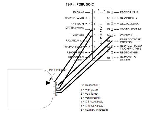
Note: Pin configurations vary by microcontroller; consult your MCU datasheet for exact pin connections.
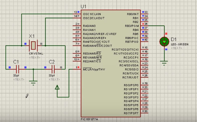
Project Example:
Connect LEDs, power, and resistors to the PICkit3.5 programmer board as shown. No crystal oscillator or capacitor is needed for this example.
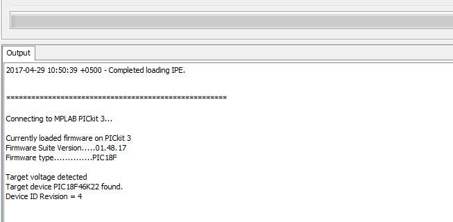
Steps to use MPLAB IPE software:
1. Download and install MPLAB IPE from the Microchip website.
2. Connect the PICkit3.5 hardware to your PC via USB.
3. Open MPLAB IPE, select your device, and click "Connect".
4. Write a program in mikroC PRO for PIC that blinks two LEDs in sinking and sourcing modes.
5. Build the project to generate a .hex file.
6. Import the .hex file into MPLAB IPE.
7. Click "Program" to upload and run the code. LEDs should blink accordingly.
Library Installation:
- Download the
xc.hlibrary file from Microchip's website compatible with your compiler. - Extract the ZIP file to a temporary folder.
- Copy the
xc.hfile to theincfolder in your XC8 compiler installation directory (default:C:\Program Files (x86)\Microchip\xc8\inc).
Example Code (PIC18F46K22 LED Blink):
#include "xc.h"  // XC8 header file

// Configuration settings
#pragma config FOSC = INTIO67, WDTE = OFF, PWRTE = OFF, MCLRE = ON, CP = OFF, BOREN = OFF, LVP = OFF, WRT = OFF

#define _XTAL_FREQ 16000000  // Define oscillator frequency

void main(void) {
    TRISDbits.TRISD1 = 0;  // Configure RD1 as output (LED1)
    TRISDbits.TRISD2 = 0;  // Configure RD2 as output (LED2)

    while(1) {
        LATDbits.LATD1 = 1;  // Turn on LED1
        LATDbits.LATD2 = 0;  // Turn off LED2
        __delay_ms(500);     // Delay 500 ms

        LATDbits.LATD1 = 0;  // Turn off LED1
        LATDbits.LATD2 = 1;  // Turn on LED2
        __delay_ms(500);     // Delay 500 ms
    }
}
Note: Modify pins and oscillator frequency according to your hardware setup.
Technical Details:
- USB Full speed 12 Mbit/s host PC interface
- Built-in overvoltage/short circuit monitor
- Diagnostic LEDs for power, busy, and error
- Supports read/write and memory clearing with verification
- Programming capability up to 512K byte flash (Programmer-to-Go)
- Stable external power supply current output voltage
- Robust interface protection
- Compatible with PIC16, PIC18, PIC24, dsPIC, and other MCUs
Comparisons with PICkit 2:
- Supports a wider range of microcontrollers
- Faster and more stable debugging experience
- Offline programming capability
- Improved interface protection
- Firmware upgradable via PC or web
- More stable power output with higher current
Features:
- Offline programming for smooth downloads and compatibility with all versions of MPLAB and MPLAB X.
- Each PICkit 3.5 has a unique serial number, allowing multiple devices to operate simultaneously under MPLAB X.
- Increased external power supply current for more stable output voltage.
- Enhanced interface protection.
- Full-speed USB 12 Mbit/s host PC interface.
- Real-time operation.
- MPLAB IDE-compliant execution with free download from Microchip.
- Built-in overvoltage and short-circuit monitor.
- Firmware upgradable via PC or web download.
- Fully enclosed design.
- Diagnostic LED indicators (power, busy, error).
- Ability to read/write microcontroller memory data.
- Memory clearing with verification of program memory.
- Peripheral freeze at the breakpoint.
- Can program up to 512K byte flash with the Programmer-to-Go feature.
Description:
The PICkit3.5 Programmer In-Circuit Debugger is a cost-effective tool designed for PIC microcontrollers, offering in-circuit logic debugging built into chips with Flash memory. It includes necessary cables and supports offline programming with full compatibility for MPLAB and MPLAB X environments. It provides stable power output, enhanced interface protection, and real-time diagnostic LEDs. It allows programming, debugging, code dumping, flashing, and firmware updates for PIC microcontrollers. PICkit3.5 uses the same connection as PICkit 3.
Principle of Work:
The PICkit 3.5 works by leveraging in-circuit logic debugging on Flash memory PIC microcontrollers. It simulates and programs PIC16, PIC18, PIC24, DSPIC, and other MCUs. It supports programming, debugging, code dumping during production, and firmware updates. Offline programming ensures smooth downloads without interruption. It has a built-in overvoltage/short-circuit monitor, real-time diagnostics, and supports programming up to 512K flash memory. The 6-pin ICSP connector interfaces with the target PIC microcontroller.
Pinout of the Module:
| Pin Number | Pin Name | Description |
|---|---|---|
| 1 | MCLR/Vpp | Connected to Master Clear external reset pin of PIC to reset MCU before programming |
| 2 | VDD | Target voltage of PIC (5V or 3.3V) |
| 3 | Ground | System ground pin |
| 4 | PGD/ICSPDAT | Program Data pin connected to ICSP data pin |
| 5 | PGC/ICSPCLK | Program Clock pin connected to ICSP clock pin |
| 6 | No connection | Reserved for future use |
Applications:
- Programming and debugging PIC microcontrollers
- Code dumping in production process
- Firmware updates and flashing
- Verifying microcontroller memory data
- Freezing peripherals at breakpoints
- Simulating and downloading PIC16, PIC18, PIC24, DSPIC, and other MCUs
- In-circuit logic debugging
- Low-cost hardware debugging and programming
- DIY projects and hobbyist use
Circuit Connections:
To connect PICkit3.5 with PIC microcontrollers (example: PIC18F1x20), use the following connections:
1. Pin 1 of PICkit3.5 → Pin 4 of PIC MCU
2. Pin 2 of PICkit3.5 → Pin 14 of PIC MCU
3. Pin 3 of PICkit3.5 → Pin 5 of PIC MCU
4. Pin 4 of PICkit3.5 → Pin 13 of PIC MCU
5. Pin 5 of PICkit3.5 → Pin 12 of PIC MCU
6. Pin 6 of PICkit3.5 → Not connected
Note: Pin configurations vary by microcontroller; consult your MCU datasheet for exact pin connections.
Project Example:
Connect LEDs, power, and resistors to the PICkit3.5 programmer board as shown. No crystal oscillator or capacitor is needed for this example.
Steps to use MPLAB IPE software:
1. Download and install MPLAB IPE from the Microchip website.
2. Connect the PICkit3.5 hardware to your PC via USB.
3. Open MPLAB IPE, select your device, and click "Connect".
4. Write a program in mikroC PRO for PIC that blinks two LEDs in sinking and sourcing modes.
5. Build the project to generate a .hex file.
6. Import the .hex file into MPLAB IPE.
7. Click "Program" to upload and run the code. LEDs should blink accordingly.
Library Installation:
- Download the
xc.hlibrary file from Microchip's website compatible with your compiler. - Extract the ZIP file to a temporary folder.
- Copy the
xc.hfile to theincfolder in your XC8 compiler installation directory (default:C:\Program Files (x86)\Microchip\xc8\inc).
Example Code (PIC18F46K22 LED Blink):
#include "xc.h"  // XC8 header file

// Configuration settings
#pragma config FOSC = INTIO67, WDTE = OFF, PWRTE = OFF, MCLRE = ON, CP = OFF, BOREN = OFF, LVP = OFF, WRT = OFF

#define _XTAL_FREQ 16000000  // Define oscillator frequency

void main(void) {
    TRISDbits.TRISD1 = 0;  // Configure RD1 as output (LED1)
    TRISDbits.TRISD2 = 0;  // Configure RD2 as output (LED2)

    while(1) {
        LATDbits.LATD1 = 1;  // Turn on LED1
        LATDbits.LATD2 = 0;  // Turn off LED2
        __delay_ms(500);     // Delay 500 ms

        LATDbits.LATD1 = 0;  // Turn off LED1
        LATDbits.LATD2 = 1;  // Turn on LED2
        __delay_ms(500);     // Delay 500 ms
    }
}
Note: Modify pins and oscillator frequency according to your hardware setup.
Technical Details:
- USB Full speed 12 Mbit/s host PC interface
- Built-in overvoltage/short circuit monitor
- Diagnostic LEDs for power, busy, and error
- Supports read/write and memory clearing with verification
- Programming capability up to 512K byte flash (Programmer-to-Go)
- Stable external power supply current output voltage
- Robust interface protection
- Compatible with PIC16, PIC18, PIC24, dsPIC, and other MCUs
Comparisons with PICkit 2:
- Supports a wider range of microcontrollers
- Faster and more stable debugging experience
- Offline programming capability
- Improved interface protection
- Firmware upgradable via PC or web
- More stable power output with higher current