Signal Generator Module 2 Way Pwm Pulse Frequency Duty Cycle Adjustable
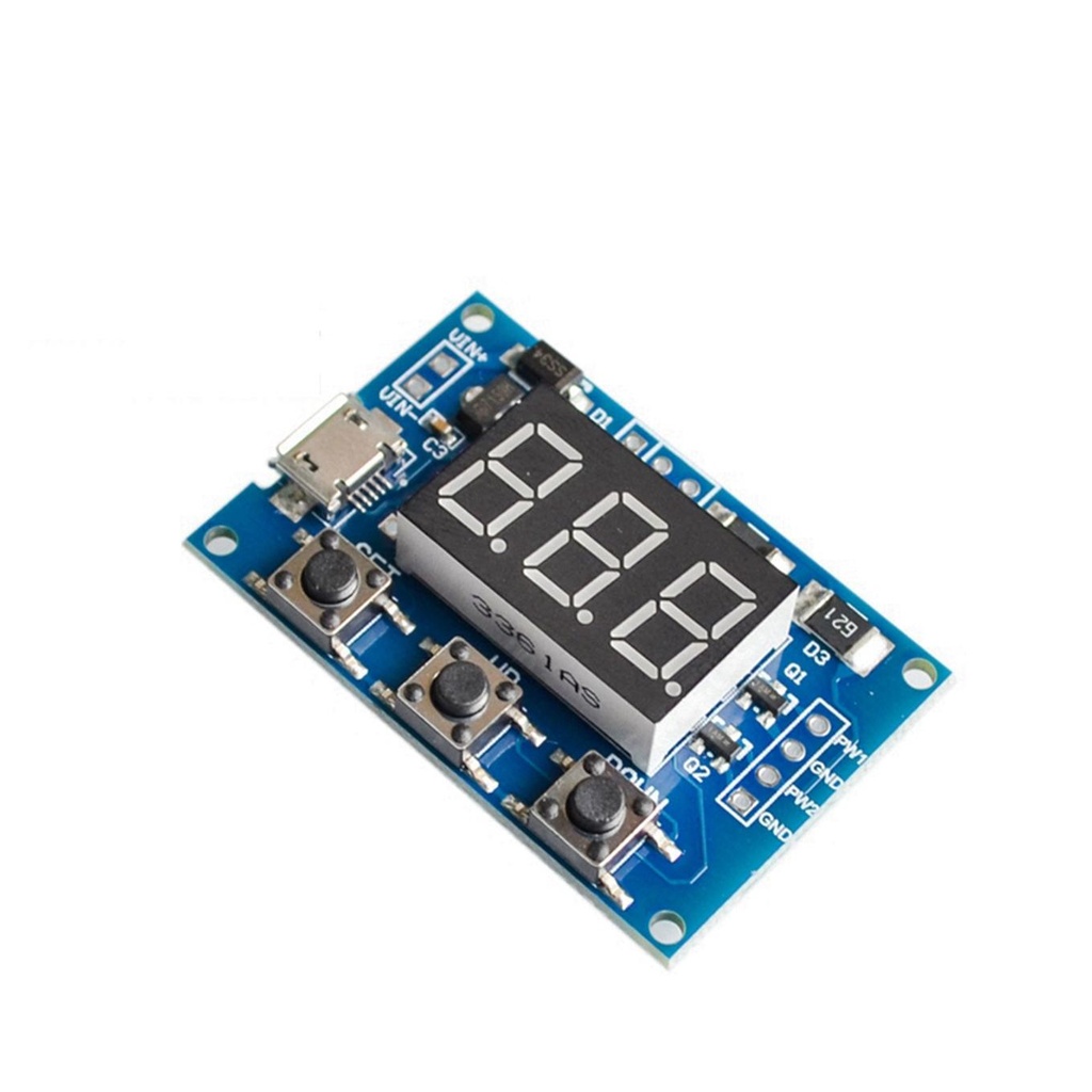
The 2-channel PWM signal generator module is designed to produce square wave signals for experiments, development, and control applications. It supports dual independent PWM outputs and is suitable for driving stepper motor drivers, microcontroller circuits, and other systems requiring pulse width modulation (PWM).
Package Includes:
- 1 x Signal Generator Module 2-Way PWM Pulse Frequency Duty Cycle Adjustable
Features:
- Dual Channel PWM: Supports two independent channels (PWM1 & PWM2).
- Adjustable Pulse Frequency: Ranges: 1Hz–999Hz, 0.1kHz–99.9kHz, 1kHz–150kHz.
- Adjustable Duty Cycle: 1% to 100% configurable.
- Stepper Motor Driver Support: Provides suitable square waves to drive motors.
- MCU Integration: Outputs are suitable for MCU-based timing and control.
- Serial Port Control: Operates over 9600 bps with specific command format.
- 3-Button Interface: Includes Set, Up, and Down buttons for local adjustments.
- Feedback Display: Indicates success ("DOWN") or failure ("FALL") of settings.
- Easy Parameter Shifting: Cycle through PWM1/2 frequency and duty via keypad.
- User-Friendly: Simple interface for configuring and operating the module.
Principle of Work:
- Power Supply: Connect a power source (5–30V or 5V via micro USB).
- Serial Control: Communicate using 9600 bps, 8 data bits, 1 stop bit, no parity.
- Command Examples:
- "S1FXXXT": Set PWM1 frequency in Hz (001–999).
- "S1FXX.XT": Set PWM1 frequency in kHz (00.1–99.9).
- "S1F:X.X.X.T": Set PWM1 frequency (0.0.1 to 1.5.0 = 1kHz to 150kHz).
- "S1DXXXT": Set PWM1 duty (001–100).
- "S2DXXXT": Set PWM2 duty (001–100).
- Using the Keypad:
- Set: Cycle through PWM1/2 frequency and duty values.
- Up/Down: Adjust selected parameter's value.
- Setting Feedback: "DOWN" for success, "FALL" for failure.
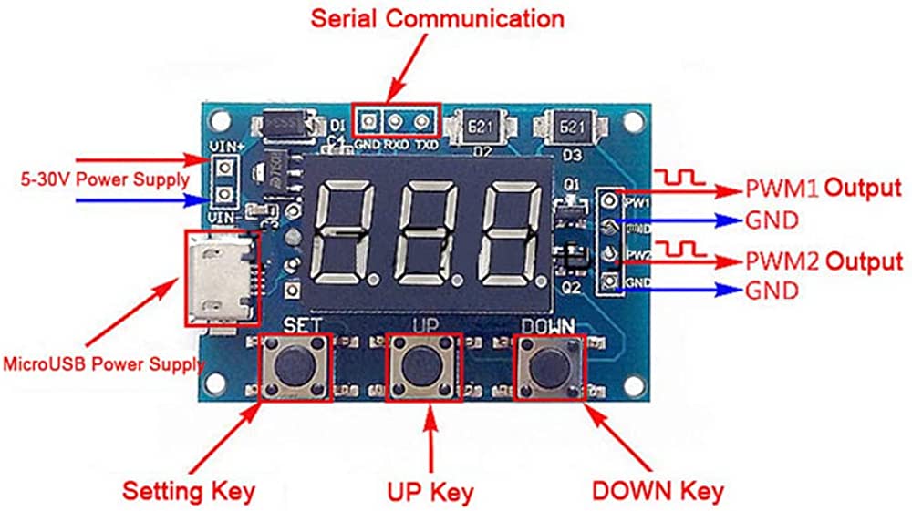
Pinout of the Module:
Applications:
- Motor Control: Drives stepper motor drivers with precision.
- Electronics Development: Signal generation for testing and prototyping.
- Microcontroller Projects: Generates timing pulses for MCU synchronization.
- Signal Simulation: Emulates square wave signals for systems testing.
- PWM Control: Controls brightness, motor speed, power delivery.
- Education: Teaches signal modulation concepts.
- DIY Projects: Suitable for hobbyist applications.
Circuit:
No additional circuit is needed. The module works out of the box.
Library:
No library is required.
Code:
No code is needed for basic operation.
Technical Details:
- Operating Voltage: 5V–30V (supports USB 5V)
- Frequency Range: 1Hz–150kHz
- Frequency Precision: ±2%
- Output Current: 8–30mA
- Output Voltage: Default 5V Vpp (adjustable with external power)
- Ambient Temperature: -30℃ to +70℃
Resources:
- Video
Comparisons:
| Feature | 2-Channel PWM Module | NE555 Signal Generator |
|---|---|---|
| Channels | 2 (PWM1 & PWM2) | 1 |
| Frequency Range | 1Hz – 150kHz | Audio range (a few Hz to 10s of kHz) |
| Duty Cycle Control | 1% – 100% (precise) | Limited or manual (via resistors) |
| PWM Support | Yes | Not explicit |
| Configuration | Serial commands and keypad | Manual via R/C network |
| Target Use | Motor/MCU control, lab, development | Basic waveform generation, education |
Features:
- Dual Channel PWM: Supports two independent channels (PWM1 & PWM2).
- Adjustable Pulse Frequency: Ranges: 1Hz–999Hz, 0.1kHz–99.9kHz, 1kHz–150kHz.
- Adjustable Duty Cycle: 1% to 100% configurable.
- Stepper Motor Driver Support: Provides suitable square waves to drive motors.
- MCU Integration: Outputs are suitable for MCU-based timing and control.
- Serial Port Control: Operates over 9600 bps with specific command format.
- 3-Button Interface: Includes Set, Up, and Down buttons for local adjustments.
- Feedback Display: Indicates success ("DOWN") or failure ("FALL") of settings.
- Easy Parameter Shifting: Cycle through PWM1/2 frequency and duty via keypad.
- User-Friendly: Simple interface for configuring and operating the module.
Principle of Work:
- Power Supply: Connect a power source (5–30V or 5V via micro USB).
- Serial Control: Communicate using 9600 bps, 8 data bits, 1 stop bit, no parity.
- Command Examples:
- "S1FXXXT": Set PWM1 frequency in Hz (001–999).
- "S1FXX.XT": Set PWM1 frequency in kHz (00.1–99.9).
- "S1F:X.X.X.T": Set PWM1 frequency (0.0.1 to 1.5.0 = 1kHz to 150kHz).
- "S1DXXXT": Set PWM1 duty (001–100).
- "S2DXXXT": Set PWM2 duty (001–100).
- Using the Keypad:
- Set: Cycle through PWM1/2 frequency and duty values.
- Up/Down: Adjust selected parameter's value.
- Setting Feedback: "DOWN" for success, "FALL" for failure.
Pinout of the Module:
Applications:
- Motor Control: Drives stepper motor drivers with precision.
- Electronics Development: Signal generation for testing and prototyping.
- Microcontroller Projects: Generates timing pulses for MCU synchronization.
- Signal Simulation: Emulates square wave signals for systems testing.
- PWM Control: Controls brightness, motor speed, power delivery.
- Education: Teaches signal modulation concepts.
- DIY Projects: Suitable for hobbyist applications.
Circuit:
No additional circuit is needed. The module works out of the box.
Library:
No library is required.
Code:
No code is needed for basic operation.
Technical Details:
- Operating Voltage: 5V–30V (supports USB 5V)
- Frequency Range: 1Hz–150kHz
- Frequency Precision: ±2%
- Output Current: 8–30mA
- Output Voltage: Default 5V Vpp (adjustable with external power)
- Ambient Temperature: -30℃ to +70℃
Resources:
- Video
Comparisons:
| Feature | 2-Channel PWM Module | NE555 Signal Generator |
|---|---|---|
| Channels | 2 (PWM1 & PWM2) | 1 |
| Frequency Range | 1Hz – 150kHz | Audio range (a few Hz to 10s of kHz) |
| Duty Cycle Control | 1% – 100% (precise) | Limited or manual (via resistors) |
| PWM Support | Yes | Not explicit |
| Configuration | Serial commands and keypad | Manual via R/C network |
| Target Use | Motor/MCU control, lab, development | Basic waveform generation, education |