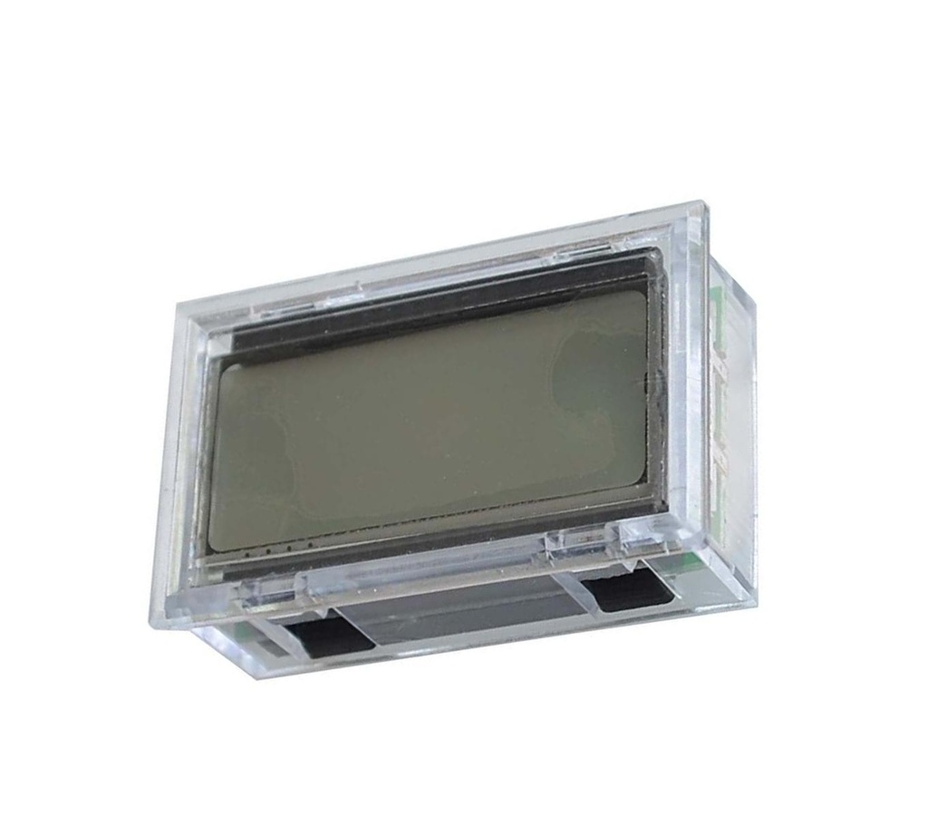
LCD for Signal Generator Pure Sine Wave Inverter IR2110" Driver Module
This LCD display is designed specifically for use with the EGS002 driver board in high-voltage, high-current environments such as pure sine wave inverters using the IR2110 driver module. It provides real-time monitoring of key parameters including voltage, current, frequency, and temperature.
Note: This LCD is only compatible with the EGS002 driver board. Shielded cable is required to prevent interference from the inverter’s high-voltage operation. Using non-shielded cable may cause severe operational issues.
the LCD offers a convenient and efficient way to monitor inverter performance, ensuring safe and stable operation.
Package Includes:
- 1 × LCD Display for Signal Generator Pure Sine Wave Inverter IR2110 Driver Module
Features:
- Designed specifically for EGS002 driver board and IR2110 module
- Real-time monitoring of voltage, current, frequency, and temperature
- Backlit display for visibility in low-light conditions
- Compact size for easy installation
- Requires shielded cable in high-voltage environments
- Low power consumption
- Clear and easy-to-read LCD interface
- Supports safe and reliable operation of pure sine wave inverters
- Versatile for use in renewable energy systems, industrial automation, home appliances, and R&D
Specification:
- Type: LCD display
- Dimensions: 32 x 22 x 12 mm
Applications:
- Renewable Energy Systems: Monitor inverter output in solar or wind systems for clean, stable power delivery.
- Industrial Automation: Ensure stable voltage and frequency for motor control and automation power supplies.
- Home Appliances: Protect sensitive electronics like refrigerators and TVs from unstable inverter power.
- Research & Development: Evaluate inverter output during device prototyping or testing.
Pin Connections:
| Pin | Description | Connection |
|---|---|---|
| 5V | Power supply input | 5V power source |
| GND | Ground | Ground |
| LCDDI | Data input | Data pin on EGS002 |
| LCDCLK | Clock input | Clock pin on EGS002 |
| LCDEN | Enable signal | Enable pin on EGS002 |
| LAMP | Backlight control | Backlight pin on EGS002 |

References:
Features:
- Designed specifically for EGS002 driver board and IR2110 module
- Real-time monitoring of voltage, current, frequency, and temperature
- Backlit display for visibility in low-light conditions
- Compact size for easy installation
- Requires shielded cable in high-voltage environments
- Low power consumption
- Clear and easy-to-read LCD interface
- Supports safe and reliable operation of pure sine wave inverters
- Versatile for use in renewable energy systems, industrial automation, home appliances, and R&D
Specification:
- Type: LCD display
- Dimensions: 32 x 22 x 12 mm
Applications:
- Renewable Energy Systems: Monitor inverter output in solar or wind systems for clean, stable power delivery.
- Industrial Automation: Ensure stable voltage and frequency for motor control and automation power supplies.
- Home Appliances: Protect sensitive electronics like refrigerators and TVs from unstable inverter power.
- Research & Development: Evaluate inverter output during device prototyping or testing.
Pin Connections:
| Pin | Description | Connection |
|---|---|---|
| 5V | Power supply input | 5V power source |
| GND | Ground | Ground |
| LCDDI | Data input | Data pin on EGS002 |
| LCDCLK | Clock input | Clock pin on EGS002 |
| LCDEN | Enable signal | Enable pin on EGS002 |
| LAMP | Backlight control | Backlight pin on EGS002 |