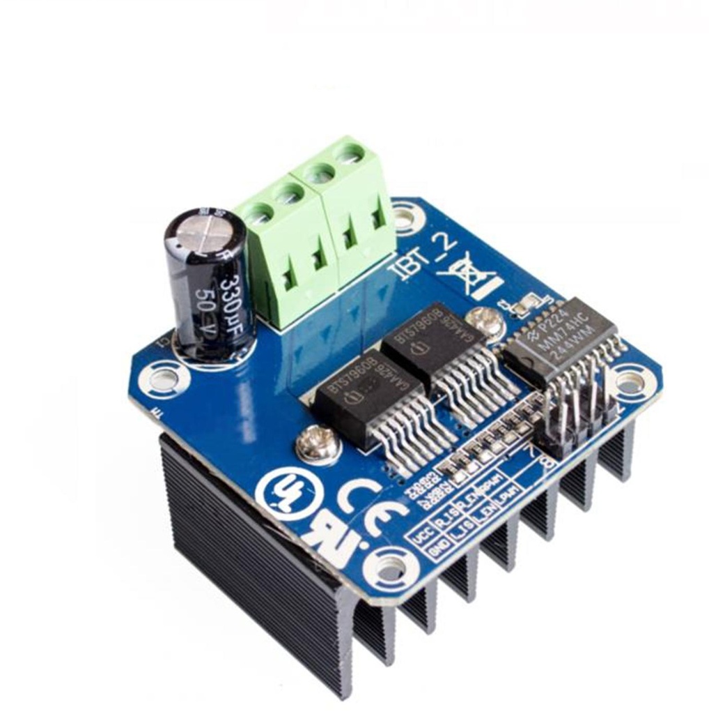
Motor Drive BTS7960 43A High Power Module
The BTS7960 Motor Driver Module is a robust and versatile module based on the BTS7960B H-bridge driver IC. It is designed to control high-power DC motors and offers a voltage range of 5V to 27V with a continuous current of 43A per channel. With its two H-bridge circuits, it enables bi-directional control of two DC motors or a single bipolar stepper motor. It uses PWM signals for speed and direction control at up to 25kHz frequency. It also features two independent current-sensing channels for safety via over-current and over-temperature protection. The compact module features screw terminals for connections and digital inputs, making it ideal for robotics and industrial automation applications.
Package Includes:
- 1 x BTS7960 Motor Driver Module
Features:
- Dual H-bridge motor driver with a voltage range of 5V to 27V
- Maximum continuous current of 43A per channel
- Bi-directional control of two DC motors or a single bipolar stepper motor
- PWM frequency range of up to 25kHz
- Two independent current-sensing channels for over-current and over-temperature protection
- Compact design with screw terminals for easy connection
- Digital inputs for controlling motor speed and direction
- Suitable for robotics, automation, and other high-power motor control applications
Principle of Work:
The module relies on the BTS7960B H-bridge IC to control DC or bipolar stepper motors in both directions. It has two H-bridge circuits, one per motor channel, and uses PWM signals to manage motor speed. The duty cycle of the PWM controls speed, while two digital inputs determine direction. Current sensing detects over-current and temperature thresholds, disabling the output if safety limits are exceeded.
Pinout of the Module:

Pin Headers:
- VCC: Module power supply – 5V
- GND: Ground
- IS-R: Input signal for detecting high current – Straight rotation
- IS-L: Input signal for detecting high current – Inverse rotation
- EN-R: Output signal for controlling motor direction – Straight rotation
- EN-L: Output signal for controlling motor direction – Inverse rotation
- PWM-R: PWM signal for motor speed – Straight rotation
- PWM-L: PWM signal for motor speed – Inverse rotation
Screw Terminals:
- 1: Motor A output
- 2: Motor A output
- 3: Motor B output
- 4: Motor B output
Note: Motor polarity depends on direction input logic levels.
Applications:
- Robotics – Drive high-power DC or stepper motors
- Automation – Conveyor belts and production lines
- Electric vehicles – Control speed and direction of motors
- CNC machines – Drive spindle and motion axes
- Home automation – Control motorized blinds, curtains, etc.
Circuit:

- LPWM to Arduino pin 6 – left motor PWM
- REN to Arduino pin 8 – right motor direction
- RPWM to Arduino pin 5 – right motor PWM
- LEN to Arduino pin 9 – left motor direction
- Potentiometer to Arduino analog pin A0 – speed control
- Logic power (E) to Arduino 5V
- Motor power (G and H) to external 5V–27V supply
- Motors connected to terminals 1-2 and 3-4
Library:
No library needed
Code:
#define RIGHT_PWM 5
#define LEFT_PWM 6
#define RIGHT_EN 8
#define LEFT_EN 9

int potentiometerValue;
int rightMotorSpeed;
int leftMotorSpeed;

void setup() {
  Serial.begin(9600);
  pinMode(RIGHT_PWM, OUTPUT);
  pinMode(LEFT_PWM, OUTPUT);
  pinMode(LEFT_EN, OUTPUT);
  pinMode(RIGHT_EN, OUTPUT);
  digitalWrite(RIGHT_EN, HIGH);
  digitalWrite(LEFT_EN, HIGH);
}

void loop() {
  potentiometerValue = analogRead(A0);

  if (potentiometerValue > 512) {
    rightMotorSpeed = map(potentiometerValue, 512, 1023, 0, 255);
    analogWrite(RIGHT_PWM, rightMotorSpeed);
    analogWrite(LEFT_PWM, 0);
  }

  if (potentiometerValue < 512) {
    leftMotorSpeed = map(potentiometerValue, 512, 0, 0, 255);
    analogWrite(LEFT_PWM, leftMotorSpeed);
    analogWrite(RIGHT_PWM, 0);
  }
}
Technical Details:
- Operating voltage: 5V to 27V
- Max continuous current per channel: 43A
- Peak current: 100A
- On-state voltage drop: 1.8V @ 25°C
- PWM frequency: Up to 25kHz
- Standby current: <1mA
- Operating temperature: -40°C to +150°C
- Dimensions: 53mm x 43mm x 27mm
- Weight: 34g
Resources:
Comparisons:
BTS7960 vs A4988
- Similarities:
- Can drive DC and stepper motors
- Use PWM for speed control
- Handle up to ~30V
- Compatible with microcontrollers like Arduino
- Differences:
- Current: BTS7960 supports up to 43A; A4988 up to 2A
- Control: BTS7960 uses dual-direction input; A4988 uses step and direction
- Microstepping: A4988 supports microstepping; BTS7960 does not
- Heat: BTS7960 handles more heat and may require cooling
- Price: BTS7960 is more expensive due to higher specs
BTS7960 is ideal for high-power applications, while A4988 is better for precision control with low-power motors.
Features:
- Dual H-bridge motor driver with a voltage range of 5V to 27V
- Maximum continuous current of 43A per channel
- Bi-directional control of two DC motors or a single bipolar stepper motor
- PWM frequency range of up to 25kHz
- Two independent current-sensing channels for over-current and over-temperature protection
- Compact design with screw terminals for easy connection
- Digital inputs for controlling motor speed and direction
- Suitable for robotics, automation, and other high-power motor control applications
Principle of Work:
The module relies on the BTS7960B H-bridge IC to control DC or bipolar stepper motors in both directions. It has two H-bridge circuits, one per motor channel, and uses PWM signals to manage motor speed. The duty cycle of the PWM controls speed, while two digital inputs determine direction. Current sensing detects over-current and temperature thresholds, disabling the output if safety limits are exceeded.
Pinout of the Module:
Pin Headers:
- VCC: Module power supply – 5V
- GND: Ground
- IS-R: Input signal for detecting high current – Straight rotation
- IS-L: Input signal for detecting high current – Inverse rotation
- EN-R: Output signal for controlling motor direction – Straight rotation
- EN-L: Output signal for controlling motor direction – Inverse rotation
- PWM-R: PWM signal for motor speed – Straight rotation
- PWM-L: PWM signal for motor speed – Inverse rotation
Screw Terminals:
- 1: Motor A output
- 2: Motor A output
- 3: Motor B output
- 4: Motor B output
Note: Motor polarity depends on direction input logic levels.
Applications:
- Robotics – Drive high-power DC or stepper motors
- Automation – Conveyor belts and production lines
- Electric vehicles – Control speed and direction of motors
- CNC machines – Drive spindle and motion axes
- Home automation – Control motorized blinds, curtains, etc.
Circuit:
- LPWM to Arduino pin 6 – left motor PWM
- REN to Arduino pin 8 – right motor direction
- RPWM to Arduino pin 5 – right motor PWM
- LEN to Arduino pin 9 – left motor direction
- Potentiometer to Arduino analog pin A0 – speed control
- Logic power (E) to Arduino 5V
- Motor power (G and H) to external 5V–27V supply
- Motors connected to terminals 1-2 and 3-4
Library:
No library needed
Code:
#define RIGHT_PWM 5
#define LEFT_PWM 6
#define RIGHT_EN 8
#define LEFT_EN 9

int potentiometerValue;
int rightMotorSpeed;
int leftMotorSpeed;

void setup() {
  Serial.begin(9600);
  pinMode(RIGHT_PWM, OUTPUT);
  pinMode(LEFT_PWM, OUTPUT);
  pinMode(LEFT_EN, OUTPUT);
  pinMode(RIGHT_EN, OUTPUT);
  digitalWrite(RIGHT_EN, HIGH);
  digitalWrite(LEFT_EN, HIGH);
}

void loop() {
  potentiometerValue = analogRead(A0);

  if (potentiometerValue > 512) {
    rightMotorSpeed = map(potentiometerValue, 512, 1023, 0, 255);
    analogWrite(RIGHT_PWM, rightMotorSpeed);
    analogWrite(LEFT_PWM, 0);
  }

  if (potentiometerValue < 512) {
    leftMotorSpeed = map(potentiometerValue, 512, 0, 0, 255);
    analogWrite(LEFT_PWM, leftMotorSpeed);
    analogWrite(RIGHT_PWM, 0);
  }
}
Technical Details:
- Operating voltage: 5V to 27V
- Max continuous current per channel: 43A
- Peak current: 100A
- On-state voltage drop: 1.8V @ 25°C
- PWM frequency: Up to 25kHz
- Standby current: <1mA
- Operating temperature: -40°C to +150°C
- Dimensions: 53mm x 43mm x 27mm
- Weight: 34g
Resources:
Comparisons:
BTS7960 vs A4988
- Similarities:
- Can drive DC and stepper motors
- Use PWM for speed control
- Handle up to ~30V
- Compatible with microcontrollers like Arduino
- Differences:
- Current: BTS7960 supports up to 43A; A4988 up to 2A
- Control: BTS7960 uses dual-direction input; A4988 uses step and direction
- Microstepping: A4988 supports microstepping; BTS7960 does not
- Heat: BTS7960 handles more heat and may require cooling
- Price: BTS7960 is more expensive due to higher specs
BTS7960 is ideal for high-power applications, while A4988 is better for precision control with low-power motors.