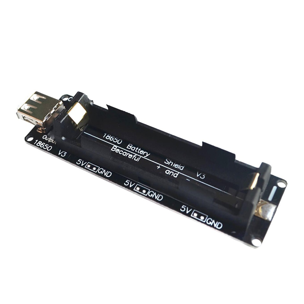
Battery Charge V3 Shield 18650 Board For Raspberry Pi With Cable
This 18650 battery shield can be used to charge and power development boards such as Arduino, ESP8266, ESP32, Raspberry Pi, and other mini PCs via USB output (Type A) or through soldering pin headers (3V or 5V) available on each side of the board.
Package Includes:
- 1 x 18650 LiFePO4 Battery Shield
Features:
- Micro USB charging port (5–8V input, up to 0.5A)
- Type-A USB output to power development boards
- 6 side output connectors:
- 3 x 3V outputs up to 1A
- 3 x 5V outputs up to 4A
- Battery charge indicators:
- Red LED: Charging
- Green LED: Charged
- Can theoretically power Raspberry Pi, Orange Pi, Banana Pi, Odroid, etc. (ensure high capacity battery)
- Basic charge control circuit – not protected against reverse polarity
- No output for battery level monitoring
Description:
The board integrates a lithium-ion battery charger circuit, protection circuit, and DC-DC boost converter. It includes LED indicators for charging status and delivers regulated 3.3V and 5V outputs via onboard connectors or USB.
It can charge the battery through the micro USB port and simultaneously power other devices via the USB Type-A port or side output connectors. Ensure proper system shutdown before cutting power to avoid corruption (especially important for Raspberry Pi).
Technical Details:
- Input Voltage: 5–8V via micro USB (up to 0.5A)
- Output Voltage:
- 5V via USB Type-A port
- 3 x 3V connectors (up to 1A total)
- 3 x 5V connectors (up to 4A total)
- Indicators: Red LED (Charging), Green LED (Charged)
- Battery Protection: Overcharge and over-discharge protection
- Warning: No reverse polarity protection
- Dimensions: 98 x 29 mm
Key Components:
| Component | Description |
|---|---|
| U9 = DW01V | 1S Li-Ion battery protection chip |
| F1 = 8205A | Dual N-Channel MOSFET |
| U2 = TC4056A | 1S Li-Ion battery charger chip |
| U7 = FP6298 | 4.5A DC-DC boost converter |
| U4, U5, U6 = 662K | 3.3V voltage regulators (XC6206 series) |
| L1 | Green LED – Battery Charged |
| L2 | Red LED – Battery Charging |
| S1 = SS14 | Schottky Diode |
| S2, S4 = SS24 | Schottky Diodes |
Charging Circuit Details:
- Battery charger: TC4056A (with 2KΩ RPROG → ~600mA charge current ±10%)
- Boost converter: FP6298, outputs ~4.99VDC with ~3.7A overcurrent protection
Images:
- Annotated PCB:

- Charging Resistor Location:

- FP6298 Typical Application Circuit:

Applications:
- Power supply for Raspberry Pi and similar mini PCs
- Battery backup for Arduino, ESP8266/ESP32
- Portable power sources for USB devices
Precautions:
- Ensure correct polarity – no reverse polarity protection
- Manually track battery charge level as there is no digital output
- Shutdown system before cutting power to avoid data corruption
Comparison & Suggestions:
This shield is ideal for portable applications where a basic regulated 5V/3.3V supply is needed from a LiFePO4 cell. However, for advanced features like battery monitoring or timed operation, consider combining with a microcontroller (like Arduino) and sensors.
Features:
- Micro USB charging port (5–8V input, up to 0.5A)
- Type-A USB output to power development boards
- 6 side output connectors:
- 3 x 3V outputs up to 1A
- 3 x 5V outputs up to 4A
- Battery charge indicators:
- Red LED: Charging
- Green LED: Charged
- Can theoretically power Raspberry Pi, Orange Pi, Banana Pi, Odroid, etc. (ensure high capacity battery)
- Basic charge control circuit – not protected against reverse polarity
- No output for battery level monitoring
Description:
The board integrates a lithium-ion battery charger circuit, protection circuit, and DC-DC boost converter. It includes LED indicators for charging status and delivers regulated 3.3V and 5V outputs via onboard connectors or USB.
It can charge the battery through the micro USB port and simultaneously power other devices via the USB Type-A port or side output connectors. Ensure proper system shutdown before cutting power to avoid corruption (especially important for Raspberry Pi).
Technical Details:
- Input Voltage: 5–8V via micro USB (up to 0.5A)
- Output Voltage:
- 5V via USB Type-A port
- 3 x 3V connectors (up to 1A total)
- 3 x 5V connectors (up to 4A total)
- Indicators: Red LED (Charging), Green LED (Charged)
- Battery Protection: Overcharge and over-discharge protection
- Warning: No reverse polarity protection
- Dimensions: 98 x 29 mm
Key Components:
| Component | Description |
|---|---|
| U9 = DW01V | 1S Li-Ion battery protection chip |
| F1 = 8205A | Dual N-Channel MOSFET |
| U2 = TC4056A | 1S Li-Ion battery charger chip |
| U7 = FP6298 | 4.5A DC-DC boost converter |
| U4, U5, U6 = 662K | 3.3V voltage regulators (XC6206 series) |
| L1 | Green LED – Battery Charged |
| L2 | Red LED – Battery Charging |
| S1 = SS14 | Schottky Diode |
| S2, S4 = SS24 | Schottky Diodes |
Charging Circuit Details:
- Battery charger: TC4056A (with 2KΩ RPROG → ~600mA charge current ±10%)
- Boost converter: FP6298, outputs ~4.99VDC with ~3.7A overcurrent protection
Images:
- Annotated PCB:
- Charging Resistor Location:
- FP6298 Typical Application Circuit:
Applications:
- Power supply for Raspberry Pi and similar mini PCs
- Battery backup for Arduino, ESP8266/ESP32
- Portable power sources for USB devices
Precautions:
- Ensure correct polarity – no reverse polarity protection
- Manually track battery charge level as there is no digital output
- Shutdown system before cutting power to avoid data corruption
Comparison & Suggestions:
This shield is ideal for portable applications where a basic regulated 5V/3.3V supply is needed from a LiFePO4 cell. However, for advanced features like battery monitoring or timed operation, consider combining with a microcontroller (like Arduino) and sensors.