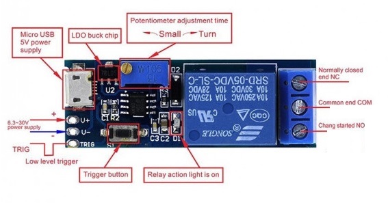
Features
- Power Supply: 5V–30V wide range, supports Micro USB 5V input
- Trigger Options: External signal or push-button trigger
- Adjustable Delay: Default range 0–24.2 seconds (adjustable via potentiometer)
- Extension Option: Add resistor/potentiometer or capacitor to increase delay time
- LED Indicators: Power, trigger status, and relay operation LEDs
- Relay Output: NO/NC/COM terminals to control AC devices
- Control Capacity: Suitable for AC 220V, max 10A (up to 2200W devices)
- Anti-Interference: High reliability in noisy environments
- No Microcontroller Required: Standalone operation without a library or MCU
Working Principle
Upon receiving a low pulse trigger (0V) via pin 2 of the NE555 timer in monostable mode:
- The output goes from LOW to HIGH
- The relay is activated and the NO and COM terminals close
- The timing capacitor C1 charges through R1
- Once 2/3 Vcc is reached across C1, the output returns to LOW and the relay deactivates
Timing Formula: T = 1.1 × R × C
Example: 22μF capacitor and 1MΩ resistor → T = 1.1 × 1,000,000 × 0.000022 = 24.2 seconds
Pinout Diagram
Internal Circuit Diagram
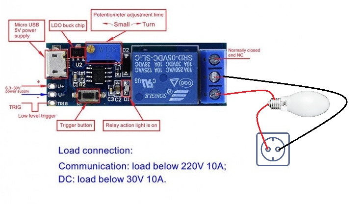
Applications
- Vehicle power delay for ignition protection
- Burglar alarms or time-controlled switches
- Sound/light delay control systems
- Prevent sudden inrush current damage in home appliances
Technical Specifications
- Dimensions: 5.4 × 1.9 × 1.8 cm
- Weight: 16g
- Operating Voltage: 5V–30V DC
- Control Voltage: AC 220V
- Relay Current: Max 10A
- Power Control: Up to 2200W
- Main Chip: NE555
Resources
- Basic Working Diagram
- Tutorials: No library or MCU needed. Fully hardware-based timing solution.
Comparison
This module is ideal for short-time accurate delays using basic analog components. For programmable and long-term precise delays (e.g., days/weeks), consider using an Arduino + DS1302 RTC + Relay Module combination for greater control and flexibility. All components are available from our store.
Features
- Power Supply: 5V–30V wide range, supports Micro USB 5V input
- Trigger Options: External signal or push-button trigger
- Adjustable Delay: Default range 0–24.2 seconds (adjustable via potentiometer)
- Extension Option: Add resistor/potentiometer or capacitor to increase delay time
- LED Indicators: Power, trigger status, and relay operation LEDs
- Relay Output: NO/NC/COM terminals to control AC devices
- Control Capacity: Suitable for AC 220V, max 10A (up to 2200W devices)
- Anti-Interference: High reliability in noisy environments
- No Microcontroller Required: Standalone operation without a library or MCU
Working Principle
Upon receiving a low pulse trigger (0V) via pin 2 of the NE555 timer in monostable mode:
- The output goes from LOW to HIGH
- The relay is activated and the NO and COM terminals close
- The timing capacitor C1 charges through R1
- Once 2/3 Vcc is reached across C1, the output returns to LOW and the relay deactivates
Timing Formula: T = 1.1 × R × C
Example: 22μF capacitor and 1MΩ resistor → T = 1.1 × 1,000,000 × 0.000022 = 24.2 seconds
Pinout Diagram
Internal Circuit Diagram
Applications
- Vehicle power delay for ignition protection
- Burglar alarms or time-controlled switches
- Sound/light delay control systems
- Prevent sudden inrush current damage in home appliances
Technical Specifications
- Dimensions: 5.4 × 1.9 × 1.8 cm
- Weight: 16g
- Operating Voltage: 5V–30V DC
- Control Voltage: AC 220V
- Relay Current: Max 10A
- Power Control: Up to 2200W
- Main Chip: NE555
Resources
- Basic Working Diagram
- Tutorials: No library or MCU needed. Fully hardware-based timing solution.
Comparison
This module is ideal for short-time accurate delays using basic analog components. For programmable and long-term precise delays (e.g., days/weeks), consider using an Arduino + DS1302 RTC + Relay Module combination for greater control and flexibility. All components are available from our store.