Features:
- Backward Compatibility: Compatible with Neo-6 and Neo-7 modules, ensuring seamless integration with existing setups.
- Versatile Connectivity: Micro USB port for easy connection to PCs and development boards like Arduino, ESP8266, and ESP32. Classic TTL TX and RX pins facilitate integration with various microprocessor systems.
- High-Performance GNSS Engine: Built on the u-blox 8 GNSS engine, supporting GPS, GLONASS, QZSS, and SBAS for accurate positioning and navigation.
- Adjustable Parameters: Parameters can be easily configured via the serial port and saved in EEPROM, offering flexibility for customization.
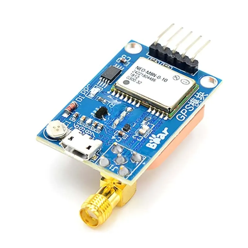
- Adaptable Antenna Interface: Equipped with an SMA interface for connecting a wide range of antennas, providing strong adaptability to different environments.
- Wide Voltage Compatibility: Compatible with 3.3V and 5V voltage levels, simplifying connections to different microprocessor systems.
- Backup Battery: Features a backup rechargeable battery onboard for maintaining settings and data integrity.
- Compact Design: Compact form factor with an onboard ceramic antenna attached to the rear of the module, optimizing space efficiency.
- Supply Voltage Options: Supports supply voltage from 3.3V to 5V DC or via USB cable for convenient power options.
- Easy Connections: Clearly labeled connections including VCC (+5V), GND (ground), TX, RX, and PPS (time pulse) for straightforward integration.
- Default Baud Rate: Comes with a default baud rate of 9600 baud for standard communication protocols.
Specifications:
- Parameters Configuration: Adjustable via serial port and saved in EEPROM
- Antenna Interface: SMA interface for versatile antenna options
- Voltage Compatibility: Supports 3.3V/5V level for easy connection to microprocessor systems
- Backup Battery: Onboard rechargeable battery for data retention
- Connectivity: Micro USB for direct connection, TTL interface for communication
- Antenna: Ceramic antenna attached to the rear of the module
- Supply Voltage: 3.3V to 5V DC or via USB cable
- Connections: VCC (+5V), GND, TX, RX, PPS
- Default Baud Rate: 9600 baud for standard communication
NEO-8M GPS Module Pinout

| Pin | Description |
|---|---|
| VIN | Module power supply - 5V |
| GND | Ground |
| RX | Receive data via serial protocol |
| TX | Send data via serial protocol |
Connecting NEO-8M GPS With Arduino:
| Module Pin | Arduino Connection |
|---|---|
| VIN | VCC 5V |
| GND | GND |
| RX | Pin 4 |
| TX | Pin 3 |
To begin, ensure all connections are properly established. Before proceeding with the code, it's crucial to integrate the necessary library into the Arduino IDE. Follow these steps:
- Download the library by clicking on this link.
- Open the Arduino IDE and navigate to Sketch > Include Library > Add .ZIP Library.
- Select the option "Add .ZIP Library" from the dropdown menu.
- Locate the downloaded .zip file and open it.
Upload the Code:
#include "TinyGPS++.h"
#include "SoftwareSerial.h"
/* This example sketch shows how to use a TinyGPS++ (TinyGPSPlus) object normally.
 It necessitates the use of SoftwareSerial and assumes a 9600-baud serial GPS device
 is connected to pins 4(rx) and 3. (tx). */
static const int RXPin = 4, TXPin = 3;
static const uint32_t GPSBaud = 9600; // The TinyGPS++ object
TinyGPSPlus gps; // The serial connection to the GPS device
SoftwareSerial ss(RXPin, TXPin);
void setup() {
 Serial.begin(115200);
 ss.begin(GPSBaud);
 Serial.println(F("DeviceExample.ino"));
 Serial.println(F("A simple demonstration of TinyGPS++ with an attached GPS module"));
 Serial.print(F("Testing TinyGPS++ library v. "));
 Serial.println(TinyGPSPlus::libraryVersion());
 Serial.println(F("by Mikal Hart"));
 Serial.println();
}
void loop() {
 // This sketch displays information every time a new sentence is correctly encoded.
 while (ss.available() > 0)
 if (gps.encode(ss.read()))
 displayInfo();
 if (millis() > 5000 && gps.charsProcessed() < 10) {
 Serial.println(F("No GPS detected: check wiring."));
 while(true);
 }
}
void displayInfo() {
 Serial.print(F("Location: "));
 if (gps.location.isValid()) {
 Serial.print(gps.location.lat(), 6);
 Serial.print(F(","));
 Serial.print(gps.location.lng(), 6);
 } else {
 Serial.print(F("INVALID"));
 }
 Serial.print(F(" Date/Time: "));
 if (gps.date.isValid()) {
 Serial.print(gps.date.month());
 Serial.print(F("/"));
 Serial.print(gps.date.day());
 Serial.print(F("/"));
 Serial.print(gps.date.year());
 } else {
 Serial.print(F("INVALID"));
 }
 Serial.print(F(" "));
 if (gps.time.isValid()) {
 if (gps.time.hour() < 10) Serial.print(F("0"));
 Serial.print(gps.time.hour());
 Serial.print(F(":"));
 if (gps.time.minute() < 10) Serial.print(F("0"));
 Serial.print(gps.time.minute());
 Serial.print(F(":"));
 if (gps.time.second() < 10) Serial.print(F("0"));
 Serial.print(gps.time.second());
 Serial.print(F("."));
 if (gps.time.centisecond() < 10) Serial.print(F("0"));
 Serial.print(gps.time.centisecond());
 } else {
 Serial.print(F("INVALID"));
 }
 Serial.println();
}
After uploading the code, you can see the output in the serial monitor.
Features:
- Backward Compatibility: Compatible with Neo-6 and Neo-7 modules, ensuring seamless integration with existing setups.
- Versatile Connectivity: Micro USB port for easy connection to PCs and development boards like Arduino, ESP8266, and ESP32. Classic TTL TX and RX pins facilitate integration with various microprocessor systems.
- High-Performance GNSS Engine: Built on the u-blox 8 GNSS engine, supporting GPS, GLONASS, QZSS, and SBAS for accurate positioning and navigation.
- Adjustable Parameters: Parameters can be easily configured via the serial port and saved in EEPROM, offering flexibility for customization.
- Adaptable Antenna Interface: Equipped with an SMA interface for connecting a wide range of antennas, providing strong adaptability to different environments.
- Wide Voltage Compatibility: Compatible with 3.3V and 5V voltage levels, simplifying connections to different microprocessor systems.
- Backup Battery: Features a backup rechargeable battery onboard for maintaining settings and data integrity.
- Compact Design: Compact form factor with an onboard ceramic antenna attached to the rear of the module, optimizing space efficiency.
- Supply Voltage Options: Supports supply voltage from 3.3V to 5V DC or via USB cable for convenient power options.
- Easy Connections: Clearly labeled connections including VCC (+5V), GND (ground), TX, RX, and PPS (time pulse) for straightforward integration.
- Default Baud Rate: Comes with a default baud rate of 9600 baud for standard communication protocols.
Specifications:
- Parameters Configuration: Adjustable via serial port and saved in EEPROM
- Antenna Interface: SMA interface for versatile antenna options
- Voltage Compatibility: Supports 3.3V/5V level for easy connection to microprocessor systems
- Backup Battery: Onboard rechargeable battery for data retention
- Connectivity: Micro USB for direct connection, TTL interface for communication
- Antenna: Ceramic antenna attached to the rear of the module
- Supply Voltage: 3.3V to 5V DC or via USB cable
- Connections: VCC (+5V), GND, TX, RX, PPS
- Default Baud Rate: 9600 baud for standard communication
NEO-8M GPS Module Pinout
| Pin | Description |
|---|---|
| VIN | Module power supply - 5V |
| GND | Ground |
| RX | Receive data via serial protocol |
| TX | Send data via serial protocol |
Connecting NEO-8M GPS With Arduino:
| Module Pin | Arduino Connection |
|---|---|
| VIN | VCC 5V |
| GND | GND |
| RX | Pin 4 |
| TX | Pin 3 |
To begin, ensure all connections are properly established. Before proceeding with the code, it's crucial to integrate the necessary library into the Arduino IDE. Follow these steps:
- Download the library by clicking on this link.
- Open the Arduino IDE and navigate to Sketch > Include Library > Add .ZIP Library.
- Select the option "Add .ZIP Library" from the dropdown menu.
- Locate the downloaded .zip file and open it.
Upload the Code:
#include "TinyGPS++.h"
#include "SoftwareSerial.h"
/* This example sketch shows how to use a TinyGPS++ (TinyGPSPlus) object normally.
 It necessitates the use of SoftwareSerial and assumes a 9600-baud serial GPS device
 is connected to pins 4(rx) and 3. (tx). */
static const int RXPin = 4, TXPin = 3;
static const uint32_t GPSBaud = 9600; // The TinyGPS++ object
TinyGPSPlus gps; // The serial connection to the GPS device
SoftwareSerial ss(RXPin, TXPin);
void setup() {
 Serial.begin(115200);
 ss.begin(GPSBaud);
 Serial.println(F("DeviceExample.ino"));
 Serial.println(F("A simple demonstration of TinyGPS++ with an attached GPS module"));
 Serial.print(F("Testing TinyGPS++ library v. "));
 Serial.println(TinyGPSPlus::libraryVersion());
 Serial.println(F("by Mikal Hart"));
 Serial.println();
}
void loop() {
 // This sketch displays information every time a new sentence is correctly encoded.
 while (ss.available() > 0)
 if (gps.encode(ss.read()))
 displayInfo();
 if (millis() > 5000 && gps.charsProcessed() < 10) {
 Serial.println(F("No GPS detected: check wiring."));
 while(true);
 }
}
void displayInfo() {
 Serial.print(F("Location: "));
 if (gps.location.isValid()) {
 Serial.print(gps.location.lat(), 6);
 Serial.print(F(","));
 Serial.print(gps.location.lng(), 6);
 } else {
 Serial.print(F("INVALID"));
 }
 Serial.print(F(" Date/Time: "));
 if (gps.date.isValid()) {
 Serial.print(gps.date.month());
 Serial.print(F("/"));
 Serial.print(gps.date.day());
 Serial.print(F("/"));
 Serial.print(gps.date.year());
 } else {
 Serial.print(F("INVALID"));
 }
 Serial.print(F(" "));
 if (gps.time.isValid()) {
 if (gps.time.hour() < 10) Serial.print(F("0"));
 Serial.print(gps.time.hour());
 Serial.print(F(":"));
 if (gps.time.minute() < 10) Serial.print(F("0"));
 Serial.print(gps.time.minute());
 Serial.print(F(":"));
 if (gps.time.second() < 10) Serial.print(F("0"));
 Serial.print(gps.time.second());
 Serial.print(F("."));
 if (gps.time.centisecond() < 10) Serial.print(F("0"));
 Serial.print(gps.time.centisecond());
 } else {
 Serial.print(F("INVALID"));
 }
 Serial.println();
}
After uploading the code, you can see the output in the serial monitor.