Features:
- Microcontroller: ATmega2560 8-bit AVR microcontroller
- Power Supply: Accepts 7–9V via Vin or Micro-USB
- Digital I/O Pins: 54 (15 with PWM support)
- Analog I/O Pins: 16 analog inputs
- Total I/O: 70 I/O pins for flexible interfacing
- Clock Speed: 16 MHz quartz crystal oscillator
- Flash Memory: 128 KB (8 KB used by bootloader)
- SRAM: 8 KB
- USB Converter: CH340 USB-UART interface
- Interfaces Supported: ICSP, SPI, I2C, 4x USART
- Timers: 6 total (2 x 8-bit, 4 x 16-bit)
- PWM Channels: 12 channels (2–16-bit resolution)
- ADC: 16 channels, 10-bit resolution
- Change Interrupts: 24 supported
- Voltage Regulators: Onboard 5V and 3.3V LDO regulators
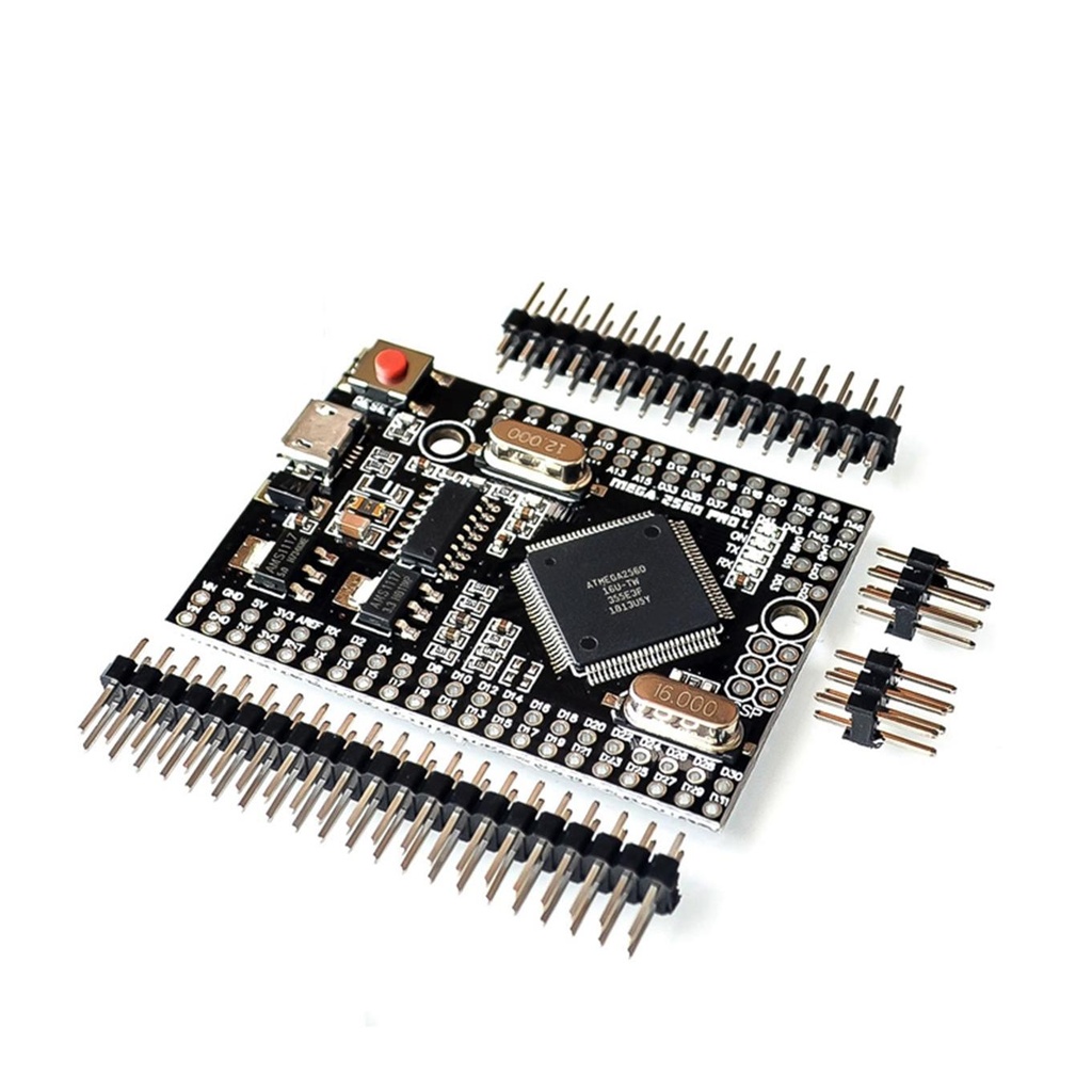
Description:
Despite its small footprint, the Mega Pro Embed retains the full feature set of the Mega 2560. Its robust design and high-quality components (such as the 16 MHz resonator) ensure reliability in industrial and hobbyist applications alike. Communication is handled via the CH340G USB-UART chip (driver installation required).
Power can be supplied via the Micro-USB port or through the Vin/GND pins. While the onboard regulator can technically tolerate up to 18V, using a 6V–9V DC supply is recommended to avoid heat buildup and potential damage.
Principle of Operation:
As with all Arduino-compatible boards, the Mega Pro Embed is based on the principles of simplicity, openness, and ease of use. Key operational highlights include:
- Open Source: Fully open hardware and software ecosystem
- User-Friendly: Easy coding via the Arduino IDE
- Extensibility: Compatible with shields and peripherals
- Cross-Platform: Works on Windows, macOS, and Linux
How It Works Internally:
- Microcontroller: Runs user code stored in Flash
- Bootloader: Enables USB programming without external hardware
- Flash Memory: Non-volatile memory for code storage
- SRAM: Temporary memory for runtime variables
- I/O Pins: Digital and analog input/output interfacing
- Clock: Keeps operations synchronized at 16 MHz
- Power Supply: Regulated 5V and 3.3V output for peripherals
- USB-UART: CH340 chip for serial communication with a PC
Pinout Diagram:

Pin Functions:
- Digital I/O: 54 pins (15 PWM-capable)
- GND: Ground connections
- AREF: Analog reference voltage for ADC
- SDA/SCL: I2C communication pins
- ICSP Header: Programming via MOSI/MISO/SCK
- USB Port: CH340 for programming and serial data
- D13 LED: Built-in LED for testing
- TX/RX LEDs: Indicate serial communication
- Crystal Oscillator: 16 MHz timing source
- Voltage Regulators: 5V and 3.3V outputs
- IOREF: Voltage reference for shields
- RESET Header: Optional external reset pin
- Power Pins: 3.3V (50mA max), 5V, GND
- Vin: Accepts 6–9V external DC input
- Analog Pins: A0–A15
- Reset Button: Restarts the board manually
- SPI Header: Alternate interface for programming and communication
- Power LED: Indicates power-on state
Common Applications:
- Weighing Machines
- Traffic Light Countdown Systems
- Smart Parking Lot Counters
- Embedded System Projects
- Home Automation
- Industrial Automation
- Medical Device Prototypes
- Emergency Lighting for Railways
Basic Circuit:
No external circuit required for basic testing—uses built-in LED on pin 13.
First-Time Setup with Arduino IDE:
- Install the Arduino IDE: Download Arduino IDE
- Install CH340 Driver: Download CH340 Driver
- Select the Board: Tools → Board → "Arduino Mega or Mega 2560"
- Select Port: Tools → Port → Choose correct COM port
- Windows: COMx
- macOS: /dev/cu.usbmodem*
- Linux: /dev/ttyACM*
- Upload Code: Write a sketch or use an example (e.g., "Blink"), click Verify, then Upload.
Example Code:
// Basic Serial and LED Test
void setup() {
  Serial.begin(9600);
  pinMode(13, OUTPUT);
  Serial.println("Serial communication initialized...");
}

void loop() {
  digitalWrite(13, HIGH);
  delay(500);
  digitalWrite(13, LOW);
  delay(500);
}
Features:
- Microcontroller: ATmega2560 8-bit AVR microcontroller
- Power Supply: Accepts 7–9V via Vin or Micro-USB
- Digital I/O Pins: 54 (15 with PWM support)
- Analog I/O Pins: 16 analog inputs
- Total I/O: 70 I/O pins for flexible interfacing
- Clock Speed: 16 MHz quartz crystal oscillator
- Flash Memory: 128 KB (8 KB used by bootloader)
- SRAM: 8 KB
- USB Converter: CH340 USB-UART interface
- Interfaces Supported: ICSP, SPI, I2C, 4x USART
- Timers: 6 total (2 x 8-bit, 4 x 16-bit)
- PWM Channels: 12 channels (2–16-bit resolution)
- ADC: 16 channels, 10-bit resolution
- Change Interrupts: 24 supported
- Voltage Regulators: Onboard 5V and 3.3V LDO regulators
Description:
Despite its small footprint, the Mega Pro Embed retains the full feature set of the Mega 2560. Its robust design and high-quality components (such as the 16 MHz resonator) ensure reliability in industrial and hobbyist applications alike. Communication is handled via the CH340G USB-UART chip (driver installation required).
Power can be supplied via the Micro-USB port or through the Vin/GND pins. While the onboard regulator can technically tolerate up to 18V, using a 6V–9V DC supply is recommended to avoid heat buildup and potential damage.
Principle of Operation:
As with all Arduino-compatible boards, the Mega Pro Embed is based on the principles of simplicity, openness, and ease of use. Key operational highlights include:
- Open Source: Fully open hardware and software ecosystem
- User-Friendly: Easy coding via the Arduino IDE
- Extensibility: Compatible with shields and peripherals
- Cross-Platform: Works on Windows, macOS, and Linux
How It Works Internally:
- Microcontroller: Runs user code stored in Flash
- Bootloader: Enables USB programming without external hardware
- Flash Memory: Non-volatile memory for code storage
- SRAM: Temporary memory for runtime variables
- I/O Pins: Digital and analog input/output interfacing
- Clock: Keeps operations synchronized at 16 MHz
- Power Supply: Regulated 5V and 3.3V output for peripherals
- USB-UART: CH340 chip for serial communication with a PC
Pinout Diagram:
Pin Functions:
- Digital I/O: 54 pins (15 PWM-capable)
- GND: Ground connections
- AREF: Analog reference voltage for ADC
- SDA/SCL: I2C communication pins
- ICSP Header: Programming via MOSI/MISO/SCK
- USB Port: CH340 for programming and serial data
- D13 LED: Built-in LED for testing
- TX/RX LEDs: Indicate serial communication
- Crystal Oscillator: 16 MHz timing source
- Voltage Regulators: 5V and 3.3V outputs
- IOREF: Voltage reference for shields
- RESET Header: Optional external reset pin
- Power Pins: 3.3V (50mA max), 5V, GND
- Vin: Accepts 6–9V external DC input
- Analog Pins: A0–A15
- Reset Button: Restarts the board manually
- SPI Header: Alternate interface for programming and communication
- Power LED: Indicates power-on state
Common Applications:
- Weighing Machines
- Traffic Light Countdown Systems
- Smart Parking Lot Counters
- Embedded System Projects
- Home Automation
- Industrial Automation
- Medical Device Prototypes
- Emergency Lighting for Railways
Basic Circuit:
No external circuit required for basic testing—uses built-in LED on pin 13.
First-Time Setup with Arduino IDE:
- Install the Arduino IDE: Download Arduino IDE
- Install CH340 Driver: Download CH340 Driver
- Select the Board: Tools → Board → "Arduino Mega or Mega 2560"
- Select Port: Tools → Port → Choose correct COM port
- Windows: COMx
- macOS: /dev/cu.usbmodem*
- Linux: /dev/ttyACM*
- Upload Code: Write a sketch or use an example (e.g., "Blink"), click Verify, then Upload.
Example Code:
// Basic Serial and LED Test
void setup() {
  Serial.begin(9600);
  pinMode(13, OUTPUT);
  Serial.println("Serial communication initialized...");
}

void loop() {
  digitalWrite(13, HIGH);
  delay(500);
  digitalWrite(13, LOW);
  delay(500);
}