Skip to Content

Arduino Pro Mini Atmega328P 3.3v/8MHz Blue (Compatible)

The Arduino Pro Mini is a compact and streamlined version of Arduino. Operating at 3.3V and 8MHz with a built-in bootloader, it offers flexibility for your projects. With no onboard USB or Serial Converter, you have the freedom to customize your connections and achieve cost-effectiveness. Unleash your creativity with this versatile and budget-friendly microcontroller.
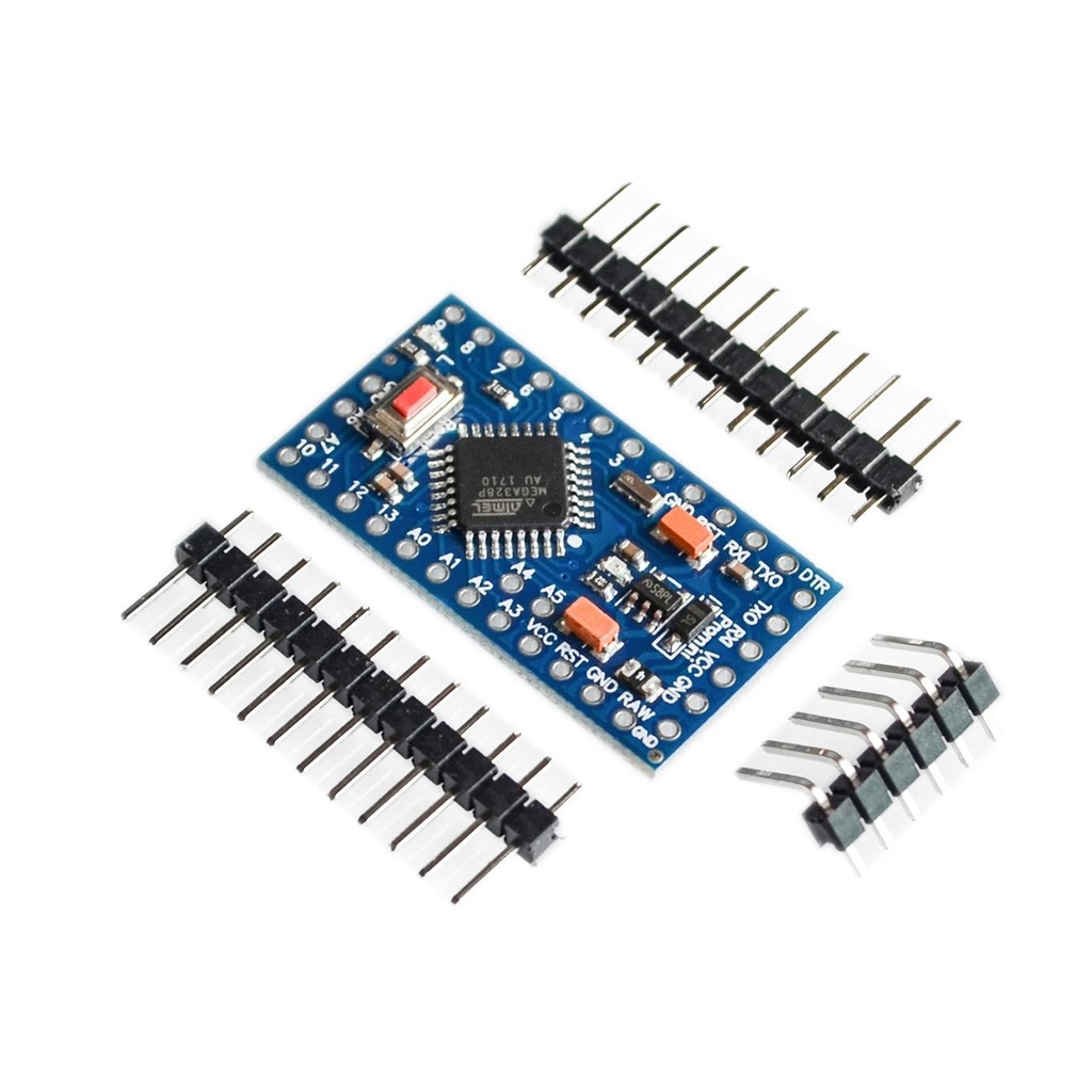
Package Includes:

  • 1 x Arduino Pro Mini ATmega328 3.3V 8Mhz Blue (Compatible)

48.30 AED 48.30 AED Tax Included
48.30 AED Tax Included

Not Available For Sale

This combination does not exist.

Terms and Conditions
30-day money-back guarantee
Shipping: 2-3 Business Days

Features

  • Microcontroller: ATmega328
  • Operating Voltage: 3.3V
  • Clock Speed: 8 MHz
  • Flash Memory: 32 KB (0.5 KB used by bootloader)
  • SRAM: 2 KB
  • EEPROM: 1 KB
  • Digital I/O Pins: 14 (of which 6 provide PWM output)
  • Analog Input Pins: 8
  • No USB interface – requires external FTDI/USB-to-Serial adapter for programming
  • Low power consumption – great for battery-operated projects
  • Compact size: 18mm x 33mm
 

Applications

  • Wearable electronics
  • IoT devices
  • Battery-powered projects
  • Sensor monitoring systems
  • Embedded systems and compact robotics

Pin Description

  • Digital I/O: D0 to D13 (PWM on D3, D5, D6, D9, D10, D11)
  • Analog Inputs: A0 to A7
  • Power Pins: VCC (3.3V), GND
  • Reset: Active-low reset pin
  • TX/RX: Serial communication pins (D0 for RX, D1 for TX)

Wiring and Programming

To program the Arduino Pro Mini, you need an FTDI USB-to-Serial adapter. Connect the following pins:

  • FTDI VCC (3.3V) → VCC
  • FTDI GND → GND
  • FTDI TX → RXI (D0)
  • FTDI RX → TXO (D1)
  • FTDI DTR → GRN (auto-reset)

In the Arduino IDE:

  • Select Board: “Arduino Pro or Pro Mini”
  • Select Processor: “ATmega328P (3.3V, 8 MHz)”
  • Select the correct COM port and upload code as usual.

Supported Protocols

  • UART (Serial)
  • I2C (Wire library, SDA on A4, SCL on A5)
  • SPI (Pins 10-13)

Example Code

This basic sketch blinks the onboard LED (usually on pin 13):

void setup() {
  pinMode(13, OUTPUT);
}

void loop() {
  digitalWrite(13, HIGH);   // LED ON
  delay(1000);              // Wait 1 second
  digitalWrite(13, LOW);    // LED OFF
  delay(1000);              // Wait 1 second
}

Important Notes

  • This board does not include a built-in USB interface. You need a 3.3V FTDI or USB-to-Serial adapter.
  • Ensure the FTDI adapter matches the board's voltage (3.3V only).
  • Use a regulated power supply if powering through VCC.