Features:
-
Based on ESP8266EX with 16MB memory.
-
Compact design with a ceramic antenna for a 90m line-of-sight range.
-
Top-side component soldering for enhanced durability and versatility.
-
Compatible with an external 2.4G Wireless SMA Antenna for an extended 150m range.
Specifications:
-
CP2104 Serial Converter
-
Memory: 16MB Flash (128 Mbit)
-
Antenna: Integrated ceramic antenna with IPEX connector for external WiFi antenna.
-
CPU Frequency: 80 MHz / 160 MHz
-
Dimensions: 34.2 mm x 25.6 mm
-
Weight: 2.5 g
-
External Antenna: SMA connector (included in the kit)
-
Operating Voltage: 3.3V
-
I/O Pins: 11 pins, including 1 analog input
-
Flash Memory: 16MB
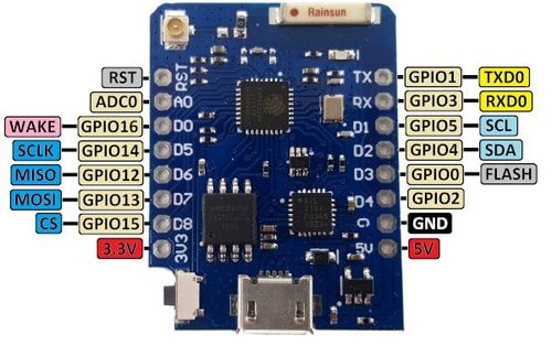
Pinout:
| Pin | Function | GPIO | Notes |
|---|---|---|---|
| D0 | GPIO16 | 16 | Can be used for wake-up from deep sleep (no interrupts) |
| D1 | GPIO5 | 5 | I2C SCL |
| D2 | GPIO4 | 4 | I2C SDA |
| D3 | GPIO0 | 0 | Connected to Flash button (pull-down for boot mode) |
| D4 | GPIO2 | 2 | Connected to built-in LED (active low) |
| D5 | GPIO14 | 14 | SPI SCK |
| D6 | GPIO12 | 12 | SPI MISO |
| D7 | GPIO13 | 13 | SPI MOSI |
| D8 | GPIO15 | 15 | SPI CS (Must be pulled low on boot) |
| TX | TXD | 1 | UART TX (debug output) |
| RX | RXD | 3 | UART RX (used for programming) |
| A0 | ADC0 | A0 | Analog input (0-1V) |
| 3V3 | 3.3V | - | 3.3V power output |
| GND | Ground | - | Ground |
| RST | Reset | - | Reset the microcontroller |
Additional Notes:
-
D0 (GPIO16): No interrupt capability.
-
A0 (ADC0): Analog input pin reads voltages from 0V to 1V. Use a voltage divider for higher voltages.
-
TX (TXD1): Used for serial debugging output.
-
RX (RXD3): Used for serial communication and programming.
-
D8 (GPIO15): Must be pulled low during boot to enable the chip.
Step-by-Step Guide for First Time Setup:
-
Install Arduino IDE:
-
Download and install from Arduino.
-
Launch the IDE after installation.
-
-
Install ESP8266 Board Support:
-
Go to
File>Preferences, and pastehttp://arduino.esp8266.com/stable/package_esp8266com_index.jsonin theAdditional Board Manager URLsfield. -
Go to
Tools>Board>Boards Manager, search for "ESP8266", and install theesp8266 by ESP8266 Communitypackage.
-
-
Connect Wemos D1 Mini Pro:
-
Use a Micro-USB cable to connect the board to your computer. Ensure the cable supports data transfer.
-
-
Select Board and Port:
-
In the IDE, go to
Tools>Board>ESP8266 Boardsand selectLOLIN(WEMOS) D1 mini Pro. -
Go to
Tools>Portand select the corresponding COM port.
-
-
Upload a Test Sketch:
-
Go to
File>Examples>ESP8266>Blinkto test the LED blink functionality.
-
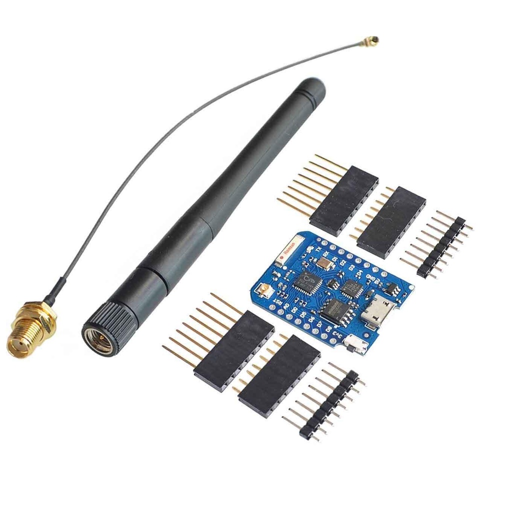
Package Includes:
-
1 x Wemos D1 Mini Pro-16
-
1 x ESP8266 Series WiFi Wireless Antenna
-
2 x Long Female Pins
-
2 x Short Female Pins
-
2 x Normal Pins
Features:
-
Based on ESP8266EX with 16MB memory.
-
Compact design with a ceramic antenna for a 90m line-of-sight range.
-
Top-side component soldering for enhanced durability and versatility.
-
Compatible with an external 2.4G Wireless SMA Antenna for an extended 150m range.
Specifications:
-
CP2104 Serial Converter
-
Memory: 16MB Flash (128 Mbit)
-
Antenna: Integrated ceramic antenna with IPEX connector for external WiFi antenna.
-
CPU Frequency: 80 MHz / 160 MHz
-
Dimensions: 34.2 mm x 25.6 mm
-
Weight: 2.5 g
-
External Antenna: SMA connector (included in the kit)
-
Operating Voltage: 3.3V
-
I/O Pins: 11 pins, including 1 analog input
-
Flash Memory: 16MB
Pinout:
| Pin | Function | GPIO | Notes |
|---|---|---|---|
| D0 | GPIO16 | 16 | Can be used for wake-up from deep sleep (no interrupts) |
| D1 | GPIO5 | 5 | I2C SCL |
| D2 | GPIO4 | 4 | I2C SDA |
| D3 | GPIO0 | 0 | Connected to Flash button (pull-down for boot mode) |
| D4 | GPIO2 | 2 | Connected to built-in LED (active low) |
| D5 | GPIO14 | 14 | SPI SCK |
| D6 | GPIO12 | 12 | SPI MISO |
| D7 | GPIO13 | 13 | SPI MOSI |
| D8 | GPIO15 | 15 | SPI CS (Must be pulled low on boot) |
| TX | TXD | 1 | UART TX (debug output) |
| RX | RXD | 3 | UART RX (used for programming) |
| A0 | ADC0 | A0 | Analog input (0-1V) |
| 3V3 | 3.3V | - | 3.3V power output |
| GND | Ground | - | Ground |
| RST | Reset | - | Reset the microcontroller |
Additional Notes:
-
D0 (GPIO16): No interrupt capability.
-
A0 (ADC0): Analog input pin reads voltages from 0V to 1V. Use a voltage divider for higher voltages.
-
TX (TXD1): Used for serial debugging output.
-
RX (RXD3): Used for serial communication and programming.
-
D8 (GPIO15): Must be pulled low during boot to enable the chip.
Step-by-Step Guide for First Time Setup:
-
Install Arduino IDE:
-
Download and install from Arduino.
-
Launch the IDE after installation.
-
-
Install ESP8266 Board Support:
-
Go to
File>Preferences, and pastehttp://arduino.esp8266.com/stable/package_esp8266com_index.jsonin theAdditional Board Manager URLsfield. -
Go to
Tools>Board>Boards Manager, search for "ESP8266", and install theesp8266 by ESP8266 Communitypackage.
-
-
Connect Wemos D1 Mini Pro:
-
Use a Micro-USB cable to connect the board to your computer. Ensure the cable supports data transfer.
-
-
Select Board and Port:
-
In the IDE, go to
Tools>Board>ESP8266 Boardsand selectLOLIN(WEMOS) D1 mini Pro. -
Go to
Tools>Portand select the corresponding COM port.
-
-
Upload a Test Sketch:
-
Go to
File>Examples>ESP8266>Blinkto test the LED blink functionality.
-
Package Includes:
-
1 x Wemos D1 Mini Pro-16
-
1 x ESP8266 Series WiFi Wireless Antenna
-
2 x Long Female Pins
-
2 x Short Female Pins
-
2 x Normal Pins