Features
- 4 independent relay channels
- 5V DC operating voltage
- Supports AC loads up to 240V and 2A per channel
- Solid-state switching without mechanical contacts
- Infrared LED and photo-Triac isolation
- Fast and silent switching
- Long operational life
- LED indication for channel status
- Compatible with microcontrollers and digital control systems
- Compact design for multiple AC load control
Principle of Operation

Each channel uses an infrared LED and photo-Triac to control the AC load. When a high-level DC control signal is applied to a channel, the internal infrared LED is activated. The infrared light triggers the photo-Triac, allowing current to flow through the connected AC load.
The control and load circuits are electrically isolated. The module uses a high-level trigger: 3.3–5.0V turns a channel ON, while 0–2.5V keeps it OFF.
Pinout
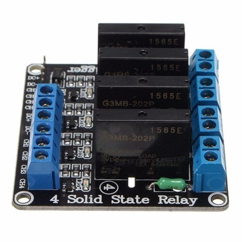
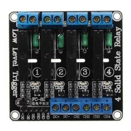
Input Connections
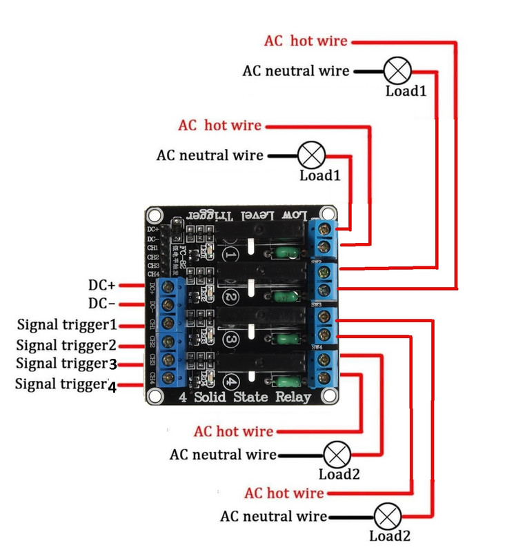
- DC+: Positive 5V DC supply.
- DC-: Ground connection.
- CH1: Control input for channel 1.
- CH2: Control input for channel 2.
- CH3: Control input for channel 3.
- CH4: Control input for channel 4.
Output Connections
- Load 1: AC load for channel 1, up to 2A at 240V AC.
- Load 2: AC load for channel 2, up to 2A at 240V AC.
- Load 3: AC load for channel 3, up to 2A at 240V AC.
- Load 4: AC load for channel 4, up to 2A at 240V AC.
Wiring
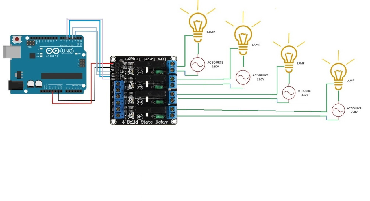
- Connect DC+ to the 5V supply.
- Connect DC- to the controller GND.
- Connect CH1–CH4 to digital output pins of the controller.
- Connect each AC load to its corresponding output terminals.
- Use HIGH to activate a channel and LOW to deactivate it.
Circuit
The example below demonstrates sequential control of four 220V lamps, with each channel turned ON for 1 second and then OFF for 1 second.
Library
No special library is required. The module can be controlled using standard Arduino digital output functions.
Code
void setup() {
  // Initialize channels 2, 3, 4, and 5 as outputs.
  pinMode(2, OUTPUT);
  pinMode(3, OUTPUT);
  pinMode(4, OUTPUT);
  pinMode(5, OUTPUT);

// Set all channels OFF.
digitalWrite(2, LOW);
digitalWrite(3, LOW);
digitalWrite(4, LOW);
digitalWrite(5, LOW);

Serial.begin(9600);
}

void loop() {
for (int channel = 2; channel <= 5; channel++) {
// Turn channel ON.
digitalWrite(channel, HIGH);
Serial.print("Channel ");
Serial.print(channel);
Serial.println(" ON");
delay(1000);

```
// Turn channel OFF.
digitalWrite(channel, LOW);
Serial.print("Channel ");
Serial.print(channel);
Serial.println(" OFF");
delay(1000);
```

}
}
Applications
- Home automation
- AC lighting control
- LED lighting systems
- Industrial automation
- Automatic test equipment
- Instrumentation systems
- Thermostat and heating control
- PLC-controlled AC loads
- Remote monitoring and control systems
- Replacement for electromechanical relays where solid-state switching is preferred
Specifications
- Supply Voltage: 5V DC
- Number of Channels: 4
- Quiescent Current: 0mA
- Operating Current: 12.5mA
- Trigger Mode: High-level trigger
- Relay OFF: DC 0–2.5V
- Relay ON: DC 3.3–5.0V
- Load Voltage: 240V AC
- Load Current: 2A per channel
- Module Life: Up to 10 million switching operations
- Maximum Switching Frequency: 5KHz
Resources
Comparison
Electro-Mechanical Relays (EMRs)
- Use coils, magnetic fields, springs, and mechanical contacts.
- Have moving parts that can wear over time.
- Can switch both AC and DC loads.
- Can support higher current loads depending on the relay.
- Produce an audible clicking sound during switching.
- More susceptible to contact arcing and sparking.
Solid State Relays (SSRs)
- Use semiconductor and optoelectronic components.
- Have no moving parts, reducing mechanical wear.
- Designed primarily for AC load switching.
- Provide fast and silent switching.
- Provide electrical isolation between control and load circuits.
- Reduce contact arcing and sparking because there are no mechanical contacts.
Safety
This module is designed to switch hazardous AC voltages. Disconnect the power before wiring and use suitable insulation, enclosure, fusing, and wiring for the connected load. Do not exceed the 240V AC and 2A rating per channel.
Features
- 4 independent relay channels
- 5V DC operating voltage
- Supports AC loads up to 240V and 2A per channel
- Solid-state switching without mechanical contacts
- Infrared LED and photo-Triac isolation
- Fast and silent switching
- Long operational life
- LED indication for channel status
- Compatible with microcontrollers and digital control systems
- Compact design for multiple AC load control
Principle of Operation
Each channel uses an infrared LED and photo-Triac to control the AC load. When a high-level DC control signal is applied to a channel, the internal infrared LED is activated. The infrared light triggers the photo-Triac, allowing current to flow through the connected AC load.
The control and load circuits are electrically isolated. The module uses a high-level trigger: 3.3–5.0V turns a channel ON, while 0–2.5V keeps it OFF.
Pinout
Input Connections
- DC+: Positive 5V DC supply.
- DC-: Ground connection.
- CH1: Control input for channel 1.
- CH2: Control input for channel 2.
- CH3: Control input for channel 3.
- CH4: Control input for channel 4.
Output Connections
- Load 1: AC load for channel 1, up to 2A at 240V AC.
- Load 2: AC load for channel 2, up to 2A at 240V AC.
- Load 3: AC load for channel 3, up to 2A at 240V AC.
- Load 4: AC load for channel 4, up to 2A at 240V AC.
Wiring
- Connect DC+ to the 5V supply.
- Connect DC- to the controller GND.
- Connect CH1–CH4 to digital output pins of the controller.
- Connect each AC load to its corresponding output terminals.
- Use HIGH to activate a channel and LOW to deactivate it.
Circuit
The example below demonstrates sequential control of four 220V lamps, with each channel turned ON for 1 second and then OFF for 1 second.
Library
No special library is required. The module can be controlled using standard Arduino digital output functions.
Code
void setup() {
  // Initialize channels 2, 3, 4, and 5 as outputs.
  pinMode(2, OUTPUT);
  pinMode(3, OUTPUT);
  pinMode(4, OUTPUT);
  pinMode(5, OUTPUT);

// Set all channels OFF.
digitalWrite(2, LOW);
digitalWrite(3, LOW);
digitalWrite(4, LOW);
digitalWrite(5, LOW);

Serial.begin(9600);
}

void loop() {
for (int channel = 2; channel <= 5; channel++) {
// Turn channel ON.
digitalWrite(channel, HIGH);
Serial.print("Channel ");
Serial.print(channel);
Serial.println(" ON");
delay(1000);

```
// Turn channel OFF.
digitalWrite(channel, LOW);
Serial.print("Channel ");
Serial.print(channel);
Serial.println(" OFF");
delay(1000);
```

}
}
Applications
- Home automation
- AC lighting control
- LED lighting systems
- Industrial automation
- Automatic test equipment
- Instrumentation systems
- Thermostat and heating control
- PLC-controlled AC loads
- Remote monitoring and control systems
- Replacement for electromechanical relays where solid-state switching is preferred
Specifications
- Supply Voltage: 5V DC
- Number of Channels: 4
- Quiescent Current: 0mA
- Operating Current: 12.5mA
- Trigger Mode: High-level trigger
- Relay OFF: DC 0–2.5V
- Relay ON: DC 3.3–5.0V
- Load Voltage: 240V AC
- Load Current: 2A per channel
- Module Life: Up to 10 million switching operations
- Maximum Switching Frequency: 5KHz
Resources
Comparison
Electro-Mechanical Relays (EMRs)
- Use coils, magnetic fields, springs, and mechanical contacts.
- Have moving parts that can wear over time.
- Can switch both AC and DC loads.
- Can support higher current loads depending on the relay.
- Produce an audible clicking sound during switching.
- More susceptible to contact arcing and sparking.
Solid State Relays (SSRs)
- Use semiconductor and optoelectronic components.
- Have no moving parts, reducing mechanical wear.
- Designed primarily for AC load switching.
- Provide fast and silent switching.
- Provide electrical isolation between control and load circuits.
- Reduce contact arcing and sparking because there are no mechanical contacts.
Safety
This module is designed to switch hazardous AC voltages. Disconnect the power before wiring and use suitable insulation, enclosure, fusing, and wiring for the connected load. Do not exceed the 240V AC and 2A rating per channel.