
Principle of Work
- White light is made up of red, green, and blue, each with different wavelengths. Their combination forms all colors.
- When white light hits a surface, the reflected wavelengths define the color we perceive.
- A color sensor uses a high-intensity white LED to project modulated light onto an object.
- A grid of color-sensitive filters and photodiodes (Bayer Pattern) detects reflected light.
- Each pixel consists of red, blue, green, and clear filters. The clear filter improves performance in low light.
- The chip addresses each photodiode, averages the results, and calculates RGB intensity to determine color.
Features
- High-Resolution Conversion of Light Intensity to Frequency
- Programmable Color and Full-Scale Output Frequency
- Power Down Feature
- Communicates Directly to Microcontroller/Arduino
- TCS3200 is an upgraded version of TCS230
- Nonlinearity Error Typically 0.2% at 50 kHz
- Stable 200 ppm/°C Temperature Coefficient
- Low-Profile Lead (Pb) Free and RoHS Compliant Surface-Mount Package
- Optimum Detection Distance: ~1cm
Specification
- Power Supply: 3.3V or 5V
- Operating Voltage: 2.7 ~ 5.5V
- Distance Range: 10 to 15mm
- Dimensions: 24 x 28.5mm
- Weight: 4.17g
Applications
- Test strip reading (medical, chemical, environmental)
- Color sorting in manufacturing
- Ambient light sensing and display calibration
- Paint and textile color matching
- Industrial automation for quality control and monitoring
- Robotics (e.g., color-based line following)
- Educational experiments in light and color sensing
Pin Connections
Header one (left side)
| Pin | Description |
|---|---|
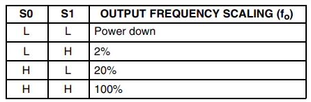
| S0 and S1 | Used to select Output Frequency Scaling: 2%, 20%, or 100% |
| LED | LED Control |
| GND | Connect to Arduino Ground |
Header two (right side)
| Pin | Description |
|---|---|
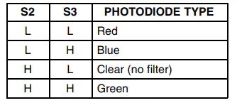
| S2 and S3 | Used to select the color array |
| OUT | Pulse frequency changes based on detected color |
| VCC | Power input: 3.3V or 5V |
Sample Project
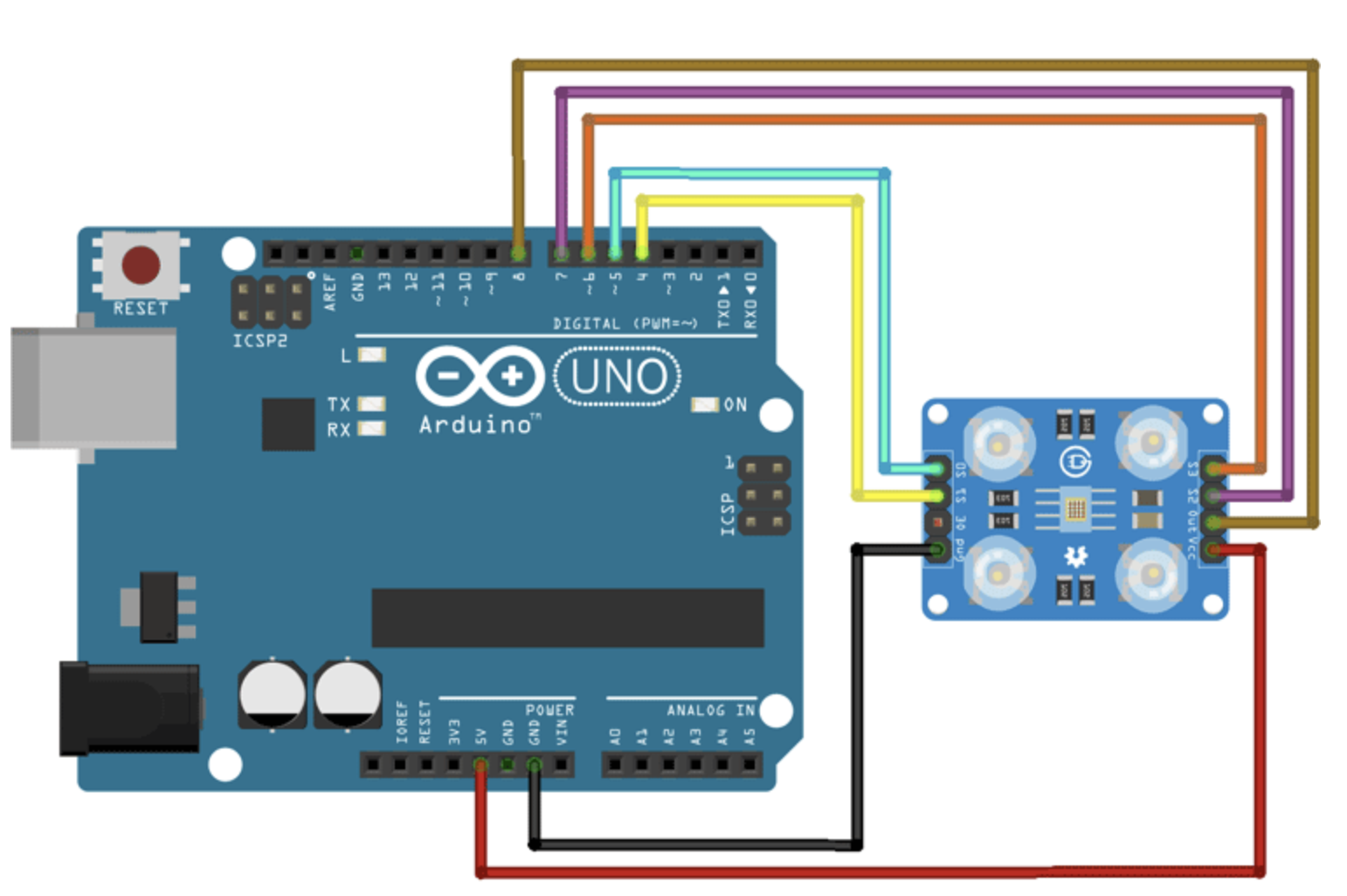
Circuit
Connect the TCS3200 to Arduino using GPIO pins 8, 7, 6, 5, and 4. Use Arduino 5V and GND to power the sensor.
Library
No external library required.
Code
#define S0_PIN 5
#define S1_PIN 4
#define S2_PIN 7
#define S3_PIN 6
#define OUT_PIN 8

void setup() {
  pinMode(S0_PIN, OUTPUT);
  pinMode(S1_PIN, OUTPUT);
  pinMode(S2_PIN, OUTPUT);
  pinMode(S3_PIN, OUTPUT);
  pinMode(OUT_PIN, INPUT);
  digitalWrite(S0_PIN, HIGH);
  digitalWrite(S1_PIN, LOW);
  Serial.begin(9600);
}

void loop() {
  int r = process_red_value();
  delay(200);
  int g = process_green_value();
  delay(200);
  int b = process_blue_value();
  delay(200);

  Serial.print("r = "); Serial.print(r);
  Serial.print(" g = "); Serial.print(g);
  Serial.print(" b = "); Serial.println(b);

  if (r < 42) Serial.println("Colour Pink");
  else if (g < 63) Serial.println("Colour Green");
  else if (r < 64) Serial.println("Colour Red");
}

int process_red_value() {
  digitalWrite(S2_PIN, LOW);
  digitalWrite(S3_PIN, LOW);
  return pulseIn(OUT_PIN, LOW);
}

int process_green_value() {
  digitalWrite(S2_PIN, HIGH);
  digitalWrite(S3_PIN, HIGH);
  return pulseIn(OUT_PIN, LOW);
}

int process_blue_value() {
  digitalWrite(S2_PIN, LOW);
  digitalWrite(S3_PIN, HIGH);
  return pulseIn(OUT_PIN, LOW);
}
Troubleshooting
- Ensure supply voltage is between 2.7V and 5.5V
- Cover the sensor to reduce ambient noise
- Check proper configuration of S0 and S1 for scaling
- Ensure S2 and S3 are properly configured
Commonly Asked Questions
1. What does a color sensor detect?
It detects the intensity of red, green, and blue light reflected from a surface.
2. How many pins are there?
The TCS3200 is an 8-pin SoC package with filters, photodiodes, and current-to-frequency converter.
3. Can it work in the dark?
Yes, it has four white LEDs for illumination.
4. What are the main parts?
White LED emitter, RGB filters (580nm, 540nm, 450nm), and photodiodes.
Notes
- Color testing may vary; consider your accuracy needs.
- S0 and S1 control output frequency (see image):
- S2 and S3 select photodiode types:
References
- Circuit Digest Tutorial
- TCS3200 Datasheet
- Arduino Currency Counter
- Sunfounder Wiki
- Addicore GitHub
- YouTube Tutorial
- Xtronical
- Last Minute Engineers
- Components101
Principle of Work
- White light is made up of red, green, and blue, each with different wavelengths. Their combination forms all colors.
- When white light hits a surface, the reflected wavelengths define the color we perceive.
- A color sensor uses a high-intensity white LED to project modulated light onto an object.
- A grid of color-sensitive filters and photodiodes (Bayer Pattern) detects reflected light.
- Each pixel consists of red, blue, green, and clear filters. The clear filter improves performance in low light.
- The chip addresses each photodiode, averages the results, and calculates RGB intensity to determine color.
Features
- High-Resolution Conversion of Light Intensity to Frequency
- Programmable Color and Full-Scale Output Frequency
- Power Down Feature
- Communicates Directly to Microcontroller/Arduino
- TCS3200 is an upgraded version of TCS230
- Nonlinearity Error Typically 0.2% at 50 kHz
- Stable 200 ppm/°C Temperature Coefficient
- Low-Profile Lead (Pb) Free and RoHS Compliant Surface-Mount Package
- Optimum Detection Distance: ~1cm
Specification
- Power Supply: 3.3V or 5V
- Operating Voltage: 2.7 ~ 5.5V
- Distance Range: 10 to 15mm
- Dimensions: 24 x 28.5mm
- Weight: 4.17g
Applications
- Test strip reading (medical, chemical, environmental)
- Color sorting in manufacturing
- Ambient light sensing and display calibration
- Paint and textile color matching
- Industrial automation for quality control and monitoring
- Robotics (e.g., color-based line following)
- Educational experiments in light and color sensing
Pin Connections
Header one (left side)
| Pin | Description |
|---|---|
| S0 and S1 | Used to select Output Frequency Scaling: 2%, 20%, or 100% |
| LED | LED Control |
| GND | Connect to Arduino Ground |
Header two (right side)
| Pin | Description |
|---|---|
| S2 and S3 | Used to select the color array |
| OUT | Pulse frequency changes based on detected color |
| VCC | Power input: 3.3V or 5V |
Sample Project
Circuit
Connect the TCS3200 to Arduino using GPIO pins 8, 7, 6, 5, and 4. Use Arduino 5V and GND to power the sensor.
Library
No external library required.
Code
#define S0_PIN 5
#define S1_PIN 4
#define S2_PIN 7
#define S3_PIN 6
#define OUT_PIN 8

void setup() {
  pinMode(S0_PIN, OUTPUT);
  pinMode(S1_PIN, OUTPUT);
  pinMode(S2_PIN, OUTPUT);
  pinMode(S3_PIN, OUTPUT);
  pinMode(OUT_PIN, INPUT);
  digitalWrite(S0_PIN, HIGH);
  digitalWrite(S1_PIN, LOW);
  Serial.begin(9600);
}

void loop() {
  int r = process_red_value();
  delay(200);
  int g = process_green_value();
  delay(200);
  int b = process_blue_value();
  delay(200);

  Serial.print("r = "); Serial.print(r);
  Serial.print(" g = "); Serial.print(g);
  Serial.print(" b = "); Serial.println(b);

  if (r < 42) Serial.println("Colour Pink");
  else if (g < 63) Serial.println("Colour Green");
  else if (r < 64) Serial.println("Colour Red");
}

int process_red_value() {
  digitalWrite(S2_PIN, LOW);
  digitalWrite(S3_PIN, LOW);
  return pulseIn(OUT_PIN, LOW);
}

int process_green_value() {
  digitalWrite(S2_PIN, HIGH);
  digitalWrite(S3_PIN, HIGH);
  return pulseIn(OUT_PIN, LOW);
}

int process_blue_value() {
  digitalWrite(S2_PIN, LOW);
  digitalWrite(S3_PIN, HIGH);
  return pulseIn(OUT_PIN, LOW);
}
Troubleshooting
- Ensure supply voltage is between 2.7V and 5.5V
- Cover the sensor to reduce ambient noise
- Check proper configuration of S0 and S1 for scaling
- Ensure S2 and S3 are properly configured
Commonly Asked Questions
1. What does a color sensor detect?
It detects the intensity of red, green, and blue light reflected from a surface.
2. How many pins are there?
The TCS3200 is an 8-pin SoC package with filters, photodiodes, and current-to-frequency converter.
3. Can it work in the dark?
Yes, it has four white LEDs for illumination.
4. What are the main parts?
White LED emitter, RGB filters (580nm, 540nm, 450nm), and photodiodes.
Notes
- Color testing may vary; consider your accuracy needs.
- S0 and S1 control output frequency (see image):
- S2 and S3 select photodiode types: