


Features
- The MAX30102 pulse oximeter and heart rate sensor can measure heart rate and oxygen saturation levels through the fingertip or earlobe.
- The MPU6050 6-axis accelerometer and gyroscope can measure motion and orientation, making this kit useful for fitness tracking and other motion-related applications.
- The PCF8563 RTC real-time clock enables the kit to keep accurate time even when not connected to the internet.
- The kit supports both AP access point and client modes for wireless connectivity.
- The 200mAh battery provides portable power for standalone operation.
- Compact enclosure with built-in LCD for easy visualization of heart rate and SpO2 data.
- Compatible with Arduino IDE and PlatformIO IDE.
Principle of Work
The module works by using the MAX30102 pulse oximeter and heart rate sensor together with the MPU6050 accelerometer and gyroscope to measure heart rate, blood oxygen level SpO2, and motion. Data is displayed on the 0.96-inch IPS LCD and can be transmitted wirelessly via WiFi or Bluetooth using the ESP32. The PCF8563 RTC maintains accurate timekeeping, and the onboard battery powers the device via micro USB charging.
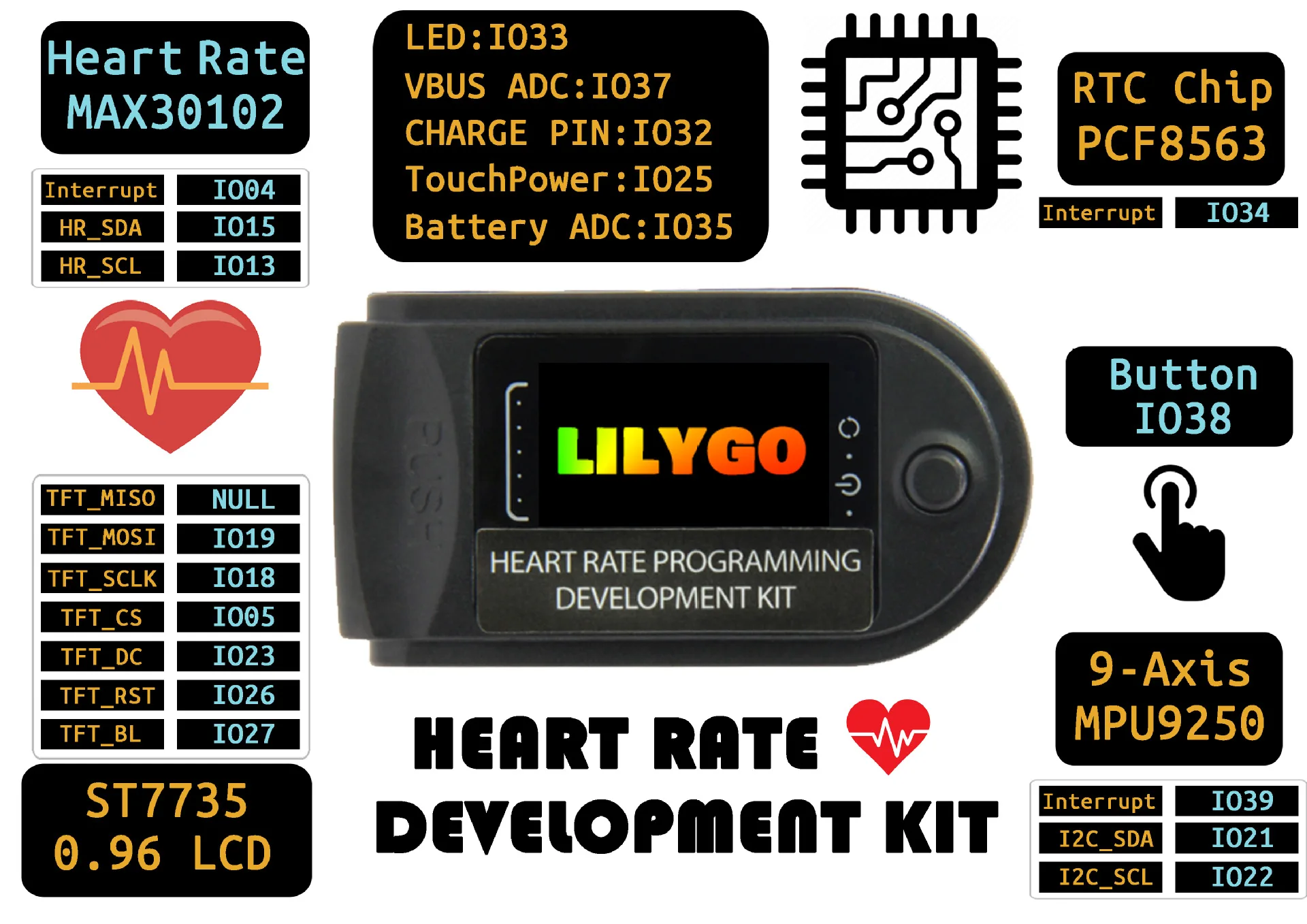
Pinout of the Module
Applications
- Fitness tracking and workout monitoring
- Wearable devices such as smartwatches and fitness bands
- Health monitoring and medical applications
- Home automation projects
- Internet of Things IoT applications
Circuit
No real circuit is required. The module can work directly by connecting it to a smartphone.

Library and Setup
-
Use Arduino IDE
- Install the correct serial port driver CP210X Driver
- Change
src/main.cpptosrc.ino - Copy the files in the lib directory to
~/Arduino/libraries, Windows users copy toDocuments/Arduino/libraries - Double-click to open
src/src.ino - Change the port to the correct port and select upload
Use PlatformIO
- Install the correct serial port driver CP210X Driver
- Open directly to change your serial port in
platformio.ini, click compile
- Note: To use
TFT_eSPI, you need to select the correct model, you need to selectSetup26_TTGO_T_Wristband.h, which has the same definition asT-Wristband, If the copy is in the lib folder, you can ignore it
In the examples directory contains two sample programs, FactoryTest is the factory test file, HeartRateMeter is a simple heart rate meter.
Code
/*
 * LilyGo-HeartRate-Kit
 * main.cpp
 * Wirte by  Lewis he , 2020
 */

#include "ArduinoOTA.h"
#include "Wire.h>"
#include "WiFi.h>"
#include "ESPmDNS.h"
#include "WiFiUdp.h"
#include "TFT_eSPI.h"
#include "OneButton.h"
#include "pcf8563.h"

#include "MAX30105.h"
#include "MPU6050.h"
#include "heartRate.h"
#include "esp_adc_cal.h"
#include "image.h"


// Has been defined in the TFT_eSPI library
// #define TFT_RST             26
// #define TFT_MISO            -1
// #define TFT_MOSI            19
// #define TFT_SCLK            18
// #define TFT_CS              5
// #define TFT_DC              23
// #define TFT_BL              27

#define  I2C_SDA_PIN             21
#define  I2C_SCL_PIN             22
#define  RTC_INT_PIN             34
#define  BATT_ADC_PIN            35
#define  VBUS_PIN                37
#define  LED_PIN                 33
#define  CHARGE_PIN              32
#define  BUTTON_PIN              38
#define  MPU_INT                 39
#define  HEATRATE_SDA            15
#define  HEATRATE_SCL            13
#define  HEATRATE_INT            4

#define  ARDUINO_OTA_UPDATE      //! Enable this line use OTA update

#define  WIFI_SSID               "Xiaomi"
#define  WIFI_PASSWD             "12345678"


TFT_eSPI    tft = TFT_eSPI();  // Invoke library, pins defined in User_Setup.h
PCF8563_Class rtc;
MPU6050     mpu;
OneButton   button(BUTTON_PIN, true);
MAX30105    particleSensor;

bool        freefallDetected = false;
int         freefallBlinkCount = 0;
char        buff[256];
bool        rtcIrq = false;
bool        initial = 1;
uint8_t     func_select = 0;
uint8_t     omm = 99;
uint8_t     xcolon = 0;
uint32_t    targetTime = 0;       // for next 1 second timeout
uint32_t    colour = 0;
int         vref = 1100;
bool        charge_indication = false;
uint8_t     hh, mm, ss ;

/*MAX30105*/
const uint8_t RATE_SIZE = 4; //Increase this for more averaging. 4 is good.
uint8_t     rates[RATE_SIZE]; //Array of heart rates
uint8_t     rateSpot = 0;
long        lastBeat = 0; //Time at which the last beat occurred
float       beatsPerMinute;
int         beatAvg;
bool        find_max30105 = false;
bool        showError = false;

void drawProgressBar(uint16_t x0, uint16_t y0, uint16_t w, uint16_t h, uint8_t percentage, uint16_t frameColor, uint16_t barColor);
void enterDeepsleep(void);

bool setupMAX30105(void)
{
    // Initialize sensor
    if (!particleSensor.begin(Wire1, 400000)) { //Use default I2C port, 400kHz speed
        Serial.println("MAX30105 was not found");
        return false;
    }
    particleSensor.setup(); //Configure sensor with default settings
    particleSensor.setPulseAmplitudeRed(0x0A); //Turn Red LED to low to indicate sensor is running
    particleSensor.setPulseAmplitudeGreen(0); //Turn off Green LED
    find_max30105 = true;
    return true;
}

void loopMAX30105(void)
{
    if (!find_max30105 && !showError) {
        tft.fillScreen(TFT_BLACK);
        tft.drawString("No detected sensor", 20, 30);
        showError = true;
        return;
    }

    if (showError) {
        return;
    }

    long irValue = particleSensor.getIR();

    if (checkForBeat(irValue) == true) {
        //We sensed a beat!
        long delta = millis() - lastBeat;
        lastBeat = millis();

        beatsPerMinute = 60 / (delta / 1000.0);

        if (beatsPerMinute < 255 && beatsPerMinute > 20) {
            rates[rateSpot++] = (uint8_t)beatsPerMinute; //Store this reading in the array
            rateSpot %= RATE_SIZE; //Wrap variable

            //Take average of readings
            beatAvg = 0;
            for (uint8_t x = 0 ; x < RATE_SIZE ; x++)
                beatAvg += rates[x];
            beatAvg /= RATE_SIZE;
        }
    }

    if (targetTime < millis()) {
        tft.fillScreen(TFT_BLACK);
        snprintf(buff, sizeof(buff), "IR=%lu BPM=%.2f", irValue, beatsPerMinute);
        tft.drawString(buff, 0, 0);
        snprintf(buff, sizeof(buff), "Avg BPM=%d", beatAvg);
        tft.drawString(buff, 0, 16);
        targetTime += 1000;
    }
    if (irValue < 50000 ) {
        digitalWrite(LED_PIN, LOW);
    } else {
        digitalWrite(LED_PIN, !digitalRead(LED_PIN));
    }
}

void checkSettings(void)
{
    Serial.println();

    Serial.print(" * Sleep Mode:            ");
    Serial.println(mpu.getSleepEnabled() ? "Enabled" : "Disabled");

    Serial.print(" * Clock Source:          ");
    switch (mpu.getClockSource()) {
    case MPU6050_CLOCK_KEEP_RESET:     Serial.println("Stops the clock and keeps the timing generator in reset"); break;
    case MPU6050_CLOCK_EXTERNAL_19MHZ: Serial.println("PLL with external 19.2MHz reference"); break;
    case MPU6050_CLOCK_EXTERNAL_32KHZ: Serial.println("PLL with external 32.768kHz reference"); break;
    case MPU6050_CLOCK_PLL_ZGYRO:      Serial.println("PLL with Z axis gyroscope reference"); break;
    case MPU6050_CLOCK_PLL_YGYRO:      Serial.println("PLL with Y axis gyroscope reference"); break;
    case MPU6050_CLOCK_PLL_XGYRO:      Serial.println("PLL with X axis gyroscope reference"); break;
    case MPU6050_CLOCK_INTERNAL_8MHZ:  Serial.println("Internal 8MHz oscillator"); break;
    }

    Serial.print(" * Accelerometer:         ");
    switch (mpu.getRange()) {
    case MPU6050_RANGE_16G:            Serial.println("+/- 16 g"); break;
    case MPU6050_RANGE_8G:             Serial.println("+/- 8 g"); break;
    case MPU6050_RANGE_4G:             Serial.println("+/- 4 g"); break;
    case MPU6050_RANGE_2G:             Serial.println("+/- 2 g"); break;
    }

    Serial.print(" * Accelerometer offsets: ");
    Serial.print(mpu.getAccelOffsetX());
    Serial.print(" / ");
    Serial.print(mpu.getAccelOffsetY());
    Serial.print(" / ");
    Serial.println(mpu.getAccelOffsetZ());

    Serial.println();
}

void doInt(void)
{
    freefallBlinkCount = 0;
    freefallDetected = true;
}

bool setupMPU6050(void)
{
    if (!mpu.begin(MPU6050_SCALE_2000DPS, MPU6050_RANGE_16G)) {
        Serial.println("setupMPU FAIL!!!");
        return false;
    }

    // If you want, you can set accelerometer offsets
    // mpu.setAccelOffsetX();
    // mpu.setAccelOffsetY();
    // mpu.setAccelOffsetZ();

    // Calibrate gyroscope. The calibration must be at rest.
    // If you don't want calibrate, comment this line.
    mpu.calibrateGyro();

    // Set threshold sensivty. Default 3.
    // If you don't want use threshold, comment this line or set 0.
    mpu.setThreshold(3);

    mpu.setAccelPowerOnDelay(MPU6050_DELAY_3MS);

    mpu.setIntFreeFallEnabled(true);
    mpu.setIntZeroMotionEnabled(true);
    mpu.setIntMotionEnabled(true);

    mpu.setDHPFMode(MPU6050_DHPF_5HZ);

    mpu.setFreeFallDetectionThreshold(17);
    mpu.setFreeFallDetectionDuration(2);

    checkSettings();
    pinMode(MPU_INT, INPUT);
    attachInterrupt(MPU_INT, doInt, CHANGE);

    return true;
}

void loopIMU(void)
{
    tft.setTextColor(TFT_GREEN, TFT_BLACK);
    tft.fillScreen(TFT_BLACK);
    tft.setTextDatum(TL_DATUM);
    Vector normAccel = mpu.readNormalizeAccel();
    Vector normGyro = mpu.readNormalizeGyro();
    snprintf(buff, sizeof(buff), "--  ACC  GYR");
    tft.drawString(buff, 0, 0);
    snprintf(buff, sizeof(buff), "x %.2f  %.2f", normAccel.XAxis, normGyro.XAxis);
    tft.drawString(buff, 0, 16);
    snprintf(buff, sizeof(buff), "y %.2f  %.2f", normAccel.YAxis, normGyro.YAxis);
    tft.drawString(buff, 0, 32);
    snprintf(buff, sizeof(buff), "z %.2f  %.2f", normAccel.ZAxis, normGyro.ZAxis);
    tft.drawString(buff, 0, 48);
    if (freefallDetected) {
        freefallDetected = false;
        Activites act = mpu.readActivites();
        Serial.println(act.isFreeFall);
        if (act.isFreeFall) {
            Serial.println("freefallDetected....");
            digitalWrite(LED_PIN, !digitalRead(LED_PIN));
            freefallBlinkCount++;
            if (freefallBlinkCount == 20) {
                digitalWrite(LED_PIN, !digitalRead(LED_PIN));
            }
        }
    }
}


bool setupWiFi(void)
{
#ifdef ARDUINO_OTA_UPDATE
    WiFi.begin(WIFI_SSID, WIFI_PASSWD);
    if (WiFi.waitForConnectResult() != WL_CONNECTED) {
        Serial.println("Connected FAIL");
        return false;
    }
#endif
    return true;
}

void setupOTA(void)
{
#ifdef ARDUINO_OTA_UPDATE
    // Port defaults to 3232
    // ArduinoOTA.setPort(3232);

    // Hostname defaults to esp3232-[MAC]
    ArduinoOTA.setHostname("esp-32");

    // No authentication by default
    // ArduinoOTA.setPassword("admin");

    // Password can be set with it's md5 value as well
    // MD5(admin) = 21232f297a57a5a743894a0e4a801fc3
    // ArduinoOTA.setPasswordHash("21232f297a57a5a743894a0e4a801fc3");

    ArduinoOTA.onStart([]() {
        String type;
        if (ArduinoOTA.getCommand() == U_FLASH)
            type = "sketch";
        else // U_SPIFFS
            type = "filesystem";

        // NOTE: if updating SPIFFS this would be the place to unmount SPIFFS using SPIFFS.end()
        Serial.println("Start updating " + type);
        tft.fillScreen(TFT_BLACK);
        tft.drawString("Updating...", tft.width() / 2 - 20, 55 );
    })
    .onEnd([]() {
        Serial.println("\nEnd");
        delay(500);
    })
    .onProgress([](unsigned int progress, unsigned int total) {
        // Serial.printf("Progress: %u%%\r", (progress / (total / 100)));
        int percentage = (progress / (total / 100));
        tft.setTextDatum(TC_DATUM);
        tft.setTextPadding(tft.textWidth(" 888% "));
        tft.drawString(String(percentage) + "%", 145, 35);
        drawProgressBar(10, 30, 120, 15, percentage, TFT_WHITE, TFT_BLUE);
    })
    .onError([](ota_error_t error) {
        Serial.printf("Error[%u]: ", error);
        if (error == OTA_AUTH_ERROR) Serial.println("Auth Failed");
        else if (error == OTA_BEGIN_ERROR) Serial.println("Begin Failed");
        else if (error == OTA_CONNECT_ERROR) Serial.println("Connect Failed");
        else if (error == OTA_RECEIVE_ERROR) Serial.println("Receive Failed");
        else if (error == OTA_END_ERROR) Serial.println("End Failed");

        tft.fillScreen(TFT_BLACK);
        tft.drawString("Update Failed", tft.width() / 2 - 20, 55 );
        delay(3000);
        initial = 1;
        targetTime = millis() + 1000;
        tft.fillScreen(TFT_BLACK);
        tft.setTextDatum(TL_DATUM);
        omm = 99;
    });

    ArduinoOTA.begin();
#endif
}

void loopOTA(void)
{
#ifdef ARDUINO_OTA_UPDATE
    ArduinoOTA.handle();
#endif
}


void setupMonitor()
{
    esp_adc_cal_characteristics_t adc_chars;
    esp_adc_cal_value_t val_type = esp_adc_cal_characterize((adc_unit_t)ADC_UNIT_1, (adc_atten_t)ADC1_CHANNEL_7, (adc_bits_width_t)ADC_WIDTH_BIT_12, 1100, &adc_chars);
    //Check type of calibration value used to characterize ADC
    if (val_type == ESP_ADC_CAL_VAL_EFUSE_VREF) {
        Serial.printf("eFuse Vref:%u mV", adc_chars.vref);
        vref = adc_chars.vref;
    } else if (val_type == ESP_ADC_CAL_VAL_EFUSE_TP) {
        Serial.printf("Two Point --> coeff_a:%umV coeff_b:%umV\n", adc_chars.coeff_a, adc_chars.coeff_b);
    } else {
        Serial.println("Default Vref: 1100mV");
    }
    pinMode(CHARGE_PIN, INPUT);
    attachInterrupt(CHARGE_PIN, [] {
        charge_indication = true;
    }, CHANGE);

    if (digitalRead(CHARGE_PIN) == LOW) {
        charge_indication = true;
    }
}

bool setupRTC(void)
{
    Wire.beginTransmission(PCF8563_SLAVE_ADDRESS);
    if (Wire.endTransmission() != 0) {
        return false;
    }

    rtc.begin(Wire);

    pinMode(RTC_INT_PIN, INPUT_PULLUP);
    attachInterrupt(RTC_INT_PIN, [] {
        rtcIrq = 1;
    }, FALLING);


    //Just test rtc interrupt start...
    rtc.disableAlarm();
    rtc.setDateTime(2019, 4, 7, 9, 5, 58);
    rtc.setAlarmByMinutes(6);
    rtc.enableAlarm();
    for (;;) {
        Serial.println(rtc.formatDateTime());
        if (rtcIrq) {
            rtcIrq = 0;
            detachInterrupt(RTC_INT_PIN);
            rtc.resetAlarm();
            break;
        }
        delay(500);
    }
    //Just test rtc interrupt end ...

    //Check if the RTC clock matches, if not, use compile time
    rtc.check();

    RTC_Date datetime = rtc.getDateTime();
    hh = datetime.hour;
    mm = datetime.minute;
    ss = datetime.second;

    return true;
}

void clickHandle(void)
{
    func_select++;
    func_select = func_select % 3;
    if (func_select == 0) {
        initial = 1;
        targetTime = 0;
        omm = 99;
        if (digitalRead(CHARGE_PIN) == LOW) {
            charge_indication = true;
        }
        tft.fillScreen(TFT_BLACK);
    }
    showError = false;
}

void setup(void)
{
    Serial.begin(115200);


    tft.init();
    tft.setRotation(1);
    tft.setSwapBytes(true);
    tft.pushImage(0, 0,  160, 80, ttgo);
    delay(2000);

    pinMode(LED_PIN, OUTPUT);
    Wire.begin(I2C_SDA_PIN, I2C_SCL_PIN);
    Wire1.begin(HEATRATE_SDA, HEATRATE_SCL);

    button.attachClick(clickHandle);
    button.attachDoubleClick(enterDeepsleep);

    tft.fillScreen(TFT_BLACK);
    tft.setTextFont(2);
    tft.setCursor(0, 0);
    tft.setTextColor(TFT_GREEN);

    if (!setupMPU6050()) {
        tft.setTextColor(TFT_RED);
        tft.println("Check MPU6050 FAIL");
        tft.setTextColor(TFT_GREEN);
    } else {
        tft.println("Check MPU6050 PASS");
    }

    if (!setupMAX30105()) {
        tft.setTextColor(TFT_RED);
        tft.println("Check MAX30105 FAIL");
        tft.setTextColor(TFT_GREEN);
    } else {
        tft.println("Check MAX30105 PASS");
    }

    if (!setupRTC()) {
        tft.setTextColor(TFT_RED);
        tft.println("Check PCF8563 FAIL");
        tft.setTextColor(TFT_GREEN);
    } else {
        tft.println("Check PCF8563 PASS");
    }

    setupMonitor();
    tft.print("Correction Vref=");
    tft.print(vref);
    tft.println(" mv");

    if (!setupWiFi()) {
        tft.setTextColor(TFT_RED);
        tft.println("Starting WiFi FAIL,Restarting...");
        tft.setTextColor(TFT_GREEN);
    } else {
        tft.println(WiFi.localIP().toString());
    }

    setupOTA();

    setCpuFrequencyMhz(80);

    delay(3000);


    func_select = 0;
    targetTime = 0;
    tft.fillScreen(TFT_BLACK);
    tft.setTextColor(TFT_YELLOW, TFT_BLACK); // Note: the new fonts do not draw the background colour


}

String getVoltage()
{
    uint16_t v = analogRead(BATT_ADC_PIN);
    float battery_voltage = ((float)v / 4095.0) * 2.0 * 3.3 * (vref / 1000.0);
    return String(battery_voltage) + "V";
}


void page1()
{
    if (charge_indication) {
        charge_indication = false;
        if (digitalRead(CHARGE_PIN) == LOW) {
            tft.pushImage(140, 55, 16, 16, charge);
        } else {
            tft.fillRect(140, 55, 16, 16, TFT_BLACK);
        }
    }

    if (targetTime < millis()) {
        RTC_Date datetime = rtc.getDateTime();
        hh = datetime.hour;
        mm = datetime.minute;
        ss = datetime.second;
        // Serial.printf("hh:%d mm:%d ss:%d\n", hh, mm, ss);
        targetTime = millis() + 1000;
        if (ss == 0 || initial) {
            initial = 0;
            tft.setTextColor(TFT_GREEN, TFT_BLACK);
            tft.setCursor (8, 60);
            tft.print(__DATE__); // This uses the standard ADAFruit small font
        }
        tft.setTextColor(TFT_BLUE, TFT_BLACK);
        tft.drawCentreString(getVoltage(), 120, 65, 1);


        // Update digital time
        uint8_t xpos = 6;
        uint8_t ypos = 0;
        if (omm != mm) { // Only redraw every minute to minimise flicker
            // Uncomment ONE of the next 2 lines, using the ghost image demonstrates text overlay as time is drawn over it
            tft.setTextColor(0x39C4, TFT_BLACK);  // Leave a 7 segment ghost image, comment out next line!
            //tft.setTextColor(TFT_BLACK, TFT_BLACK); // Set font colour to black to wipe image
            // Font 7 is to show a pseudo 7 segment display.
            // Font 7 only contains characters [space] 0 1 2 3 4 5 6 7 8 9 0 : .
            tft.drawString("88:88", xpos, ypos, 7); // Overwrite the text to clear it
            tft.setTextColor(0xFBE0, TFT_BLACK); // Orange
            omm = mm;

            if (hh < 10) xpos += tft.drawChar('0', xpos, ypos, 7);
            xpos += tft.drawNumber(hh, xpos, ypos, 7);
            xcolon = xpos;
            xpos += tft.drawChar(':', xpos, ypos, 7);
            if (mm < 10) xpos += tft.drawChar('0', xpos, ypos, 7);
            tft.drawNumber(mm, xpos, ypos, 7);
        }

        if (ss % 2) { // Flash the colon
            tft.setTextColor(0x39C4, TFT_BLACK);
            xpos += tft.drawChar(':', xcolon, ypos, 7);
            tft.setTextColor(0xFBE0, TFT_BLACK);
        } else {
            tft.drawChar(':', xcolon, ypos, 7);
        }
    }
}

void loop()
{
    loopOTA();
    button.tick();
    switch (func_select) {
    case 0:
        page1();
        break;
    case 1:
        if (targetTime < millis()) {
            targetTime += 200;
            loopIMU();
        }
        break;
    case 2:
        loopMAX30105();
        break;
    default:
        break;
    }
}

void enterDeepsleep()
{
    tft.fillScreen(TFT_BLACK);
    tft.setTextColor(TFT_GREEN, TFT_BLACK);
    tft.setTextDatum(MC_DATUM);
    tft.drawString("Press again to wake up",  tft.width() / 2, tft.height() / 2 );
    mpu.setSleepEnabled(true);
    Serial.println("Go to Sleep");
    delay(3000);
    tft.writecommand(ST7735_DISPOFF);
    tft.writecommand(ST7735_SLPIN);
    esp_sleep_enable_ext1_wakeup(GPIO_SEL_38, ESP_EXT1_WAKEUP_ALL_LOW);
    esp_deep_sleep_start();
}


void drawProgressBar(uint16_t x0, uint16_t y0, uint16_t w, uint16_t h, uint8_t percentage, uint16_t frameColor, uint16_t barColor)
{
    if (percentage == 0) {
        tft.fillRoundRect(x0, y0, w, h, 3, TFT_BLACK);
    }
    uint8_t margin = 2;
    uint16_t barHeight = h - 2 * margin;
    uint16_t barWidth = w - 2 * margin;
    tft.drawRoundRect(x0, y0, w, h, 3, frameColor);
    tft.fillRect(x0 + margin, y0 + margin, barWidth * percentage / 100.0, barHeight, barColor);
}
Technical Details
- Processor ESP32-D0WDQ6-V3 dual-core 240 MHz
- 600 DMIPS performance
- 520KB SRAM and 448KB ROM
- WiFi 802.11 b g n and Bluetooth v4.2
- 0.96 inch IPS LCD 80x160 resolution
- MAX30102 heart rate sensor
- LIS2DH12 3-axis accelerometer
- RTC PCF8563
- 200mAh rechargeable battery
- Charging voltage 5V current 500mA
Resources
Comparisons
- The LilyGo HeartRate Kit provides an all-in-one solution with ESP32, display, sensors, and wireless connectivity.
- The MAX30102 alone requires external microcontroller, circuit design, and programming.
- The development kit is more user friendly and suitable for rapid prototyping and IoT projects.
Features
- The MAX30102 pulse oximeter and heart rate sensor can measure heart rate and oxygen saturation levels through the fingertip or earlobe.
- The MPU6050 6-axis accelerometer and gyroscope can measure motion and orientation, making this kit useful for fitness tracking and other motion-related applications.
- The PCF8563 RTC real-time clock enables the kit to keep accurate time even when not connected to the internet.
- The kit supports both AP access point and client modes for wireless connectivity.
- The 200mAh battery provides portable power for standalone operation.
- Compact enclosure with built-in LCD for easy visualization of heart rate and SpO2 data.
- Compatible with Arduino IDE and PlatformIO IDE.
Principle of Work
The module works by using the MAX30102 pulse oximeter and heart rate sensor together with the MPU6050 accelerometer and gyroscope to measure heart rate, blood oxygen level SpO2, and motion. Data is displayed on the 0.96-inch IPS LCD and can be transmitted wirelessly via WiFi or Bluetooth using the ESP32. The PCF8563 RTC maintains accurate timekeeping, and the onboard battery powers the device via micro USB charging.
Pinout of the Module
Applications
- Fitness tracking and workout monitoring
- Wearable devices such as smartwatches and fitness bands
- Health monitoring and medical applications
- Home automation projects
- Internet of Things IoT applications
Circuit
No real circuit is required. The module can work directly by connecting it to a smartphone.
Library and Setup
-
Use Arduino IDE
- Install the correct serial port driver CP210X Driver
- Change
src/main.cpptosrc.ino - Copy the files in the lib directory to
~/Arduino/libraries, Windows users copy toDocuments/Arduino/libraries - Double-click to open
src/src.ino - Change the port to the correct port and select upload
Use PlatformIO
- Install the correct serial port driver CP210X Driver
- Open directly to change your serial port in
platformio.ini, click compile
- Note: To use
TFT_eSPI, you need to select the correct model, you need to selectSetup26_TTGO_T_Wristband.h, which has the same definition asT-Wristband, If the copy is in the lib folder, you can ignore it
In the examples directory contains two sample programs, FactoryTest is the factory test file, HeartRateMeter is a simple heart rate meter.
Code
/*
 * LilyGo-HeartRate-Kit
 * main.cpp
 * Wirte by  Lewis he , 2020
 */

#include "ArduinoOTA.h"
#include "Wire.h>"
#include "WiFi.h>"
#include "ESPmDNS.h"
#include "WiFiUdp.h"
#include "TFT_eSPI.h"
#include "OneButton.h"
#include "pcf8563.h"

#include "MAX30105.h"
#include "MPU6050.h"
#include "heartRate.h"
#include "esp_adc_cal.h"
#include "image.h"


// Has been defined in the TFT_eSPI library
// #define TFT_RST             26
// #define TFT_MISO            -1
// #define TFT_MOSI            19
// #define TFT_SCLK            18
// #define TFT_CS              5
// #define TFT_DC              23
// #define TFT_BL              27

#define  I2C_SDA_PIN             21
#define  I2C_SCL_PIN             22
#define  RTC_INT_PIN             34
#define  BATT_ADC_PIN            35
#define  VBUS_PIN                37
#define  LED_PIN                 33
#define  CHARGE_PIN              32
#define  BUTTON_PIN              38
#define  MPU_INT                 39
#define  HEATRATE_SDA            15
#define  HEATRATE_SCL            13
#define  HEATRATE_INT            4

#define  ARDUINO_OTA_UPDATE      //! Enable this line use OTA update

#define  WIFI_SSID               "Xiaomi"
#define  WIFI_PASSWD             "12345678"


TFT_eSPI    tft = TFT_eSPI();  // Invoke library, pins defined in User_Setup.h
PCF8563_Class rtc;
MPU6050     mpu;
OneButton   button(BUTTON_PIN, true);
MAX30105    particleSensor;

bool        freefallDetected = false;
int         freefallBlinkCount = 0;
char        buff[256];
bool        rtcIrq = false;
bool        initial = 1;
uint8_t     func_select = 0;
uint8_t     omm = 99;
uint8_t     xcolon = 0;
uint32_t    targetTime = 0;       // for next 1 second timeout
uint32_t    colour = 0;
int         vref = 1100;
bool        charge_indication = false;
uint8_t     hh, mm, ss ;

/*MAX30105*/
const uint8_t RATE_SIZE = 4; //Increase this for more averaging. 4 is good.
uint8_t     rates[RATE_SIZE]; //Array of heart rates
uint8_t     rateSpot = 0;
long        lastBeat = 0; //Time at which the last beat occurred
float       beatsPerMinute;
int         beatAvg;
bool        find_max30105 = false;
bool        showError = false;

void drawProgressBar(uint16_t x0, uint16_t y0, uint16_t w, uint16_t h, uint8_t percentage, uint16_t frameColor, uint16_t barColor);
void enterDeepsleep(void);

bool setupMAX30105(void)
{
    // Initialize sensor
    if (!particleSensor.begin(Wire1, 400000)) { //Use default I2C port, 400kHz speed
        Serial.println("MAX30105 was not found");
        return false;
    }
    particleSensor.setup(); //Configure sensor with default settings
    particleSensor.setPulseAmplitudeRed(0x0A); //Turn Red LED to low to indicate sensor is running
    particleSensor.setPulseAmplitudeGreen(0); //Turn off Green LED
    find_max30105 = true;
    return true;
}

void loopMAX30105(void)
{
    if (!find_max30105 && !showError) {
        tft.fillScreen(TFT_BLACK);
        tft.drawString("No detected sensor", 20, 30);
        showError = true;
        return;
    }

    if (showError) {
        return;
    }

    long irValue = particleSensor.getIR();

    if (checkForBeat(irValue) == true) {
        //We sensed a beat!
        long delta = millis() - lastBeat;
        lastBeat = millis();

        beatsPerMinute = 60 / (delta / 1000.0);

        if (beatsPerMinute < 255 && beatsPerMinute > 20) {
            rates[rateSpot++] = (uint8_t)beatsPerMinute; //Store this reading in the array
            rateSpot %= RATE_SIZE; //Wrap variable

            //Take average of readings
            beatAvg = 0;
            for (uint8_t x = 0 ; x < RATE_SIZE ; x++)
                beatAvg += rates[x];
            beatAvg /= RATE_SIZE;
        }
    }

    if (targetTime < millis()) {
        tft.fillScreen(TFT_BLACK);
        snprintf(buff, sizeof(buff), "IR=%lu BPM=%.2f", irValue, beatsPerMinute);
        tft.drawString(buff, 0, 0);
        snprintf(buff, sizeof(buff), "Avg BPM=%d", beatAvg);
        tft.drawString(buff, 0, 16);
        targetTime += 1000;
    }
    if (irValue < 50000 ) {
        digitalWrite(LED_PIN, LOW);
    } else {
        digitalWrite(LED_PIN, !digitalRead(LED_PIN));
    }
}

void checkSettings(void)
{
    Serial.println();

    Serial.print(" * Sleep Mode:            ");
    Serial.println(mpu.getSleepEnabled() ? "Enabled" : "Disabled");

    Serial.print(" * Clock Source:          ");
    switch (mpu.getClockSource()) {
    case MPU6050_CLOCK_KEEP_RESET:     Serial.println("Stops the clock and keeps the timing generator in reset"); break;
    case MPU6050_CLOCK_EXTERNAL_19MHZ: Serial.println("PLL with external 19.2MHz reference"); break;
    case MPU6050_CLOCK_EXTERNAL_32KHZ: Serial.println("PLL with external 32.768kHz reference"); break;
    case MPU6050_CLOCK_PLL_ZGYRO:      Serial.println("PLL with Z axis gyroscope reference"); break;
    case MPU6050_CLOCK_PLL_YGYRO:      Serial.println("PLL with Y axis gyroscope reference"); break;
    case MPU6050_CLOCK_PLL_XGYRO:      Serial.println("PLL with X axis gyroscope reference"); break;
    case MPU6050_CLOCK_INTERNAL_8MHZ:  Serial.println("Internal 8MHz oscillator"); break;
    }

    Serial.print(" * Accelerometer:         ");
    switch (mpu.getRange()) {
    case MPU6050_RANGE_16G:            Serial.println("+/- 16 g"); break;
    case MPU6050_RANGE_8G:             Serial.println("+/- 8 g"); break;
    case MPU6050_RANGE_4G:             Serial.println("+/- 4 g"); break;
    case MPU6050_RANGE_2G:             Serial.println("+/- 2 g"); break;
    }

    Serial.print(" * Accelerometer offsets: ");
    Serial.print(mpu.getAccelOffsetX());
    Serial.print(" / ");
    Serial.print(mpu.getAccelOffsetY());
    Serial.print(" / ");
    Serial.println(mpu.getAccelOffsetZ());

    Serial.println();
}

void doInt(void)
{
    freefallBlinkCount = 0;
    freefallDetected = true;
}

bool setupMPU6050(void)
{
    if (!mpu.begin(MPU6050_SCALE_2000DPS, MPU6050_RANGE_16G)) {
        Serial.println("setupMPU FAIL!!!");
        return false;
    }

    // If you want, you can set accelerometer offsets
    // mpu.setAccelOffsetX();
    // mpu.setAccelOffsetY();
    // mpu.setAccelOffsetZ();

    // Calibrate gyroscope. The calibration must be at rest.
    // If you don't want calibrate, comment this line.
    mpu.calibrateGyro();

    // Set threshold sensivty. Default 3.
    // If you don't want use threshold, comment this line or set 0.
    mpu.setThreshold(3);

    mpu.setAccelPowerOnDelay(MPU6050_DELAY_3MS);

    mpu.setIntFreeFallEnabled(true);
    mpu.setIntZeroMotionEnabled(true);
    mpu.setIntMotionEnabled(true);

    mpu.setDHPFMode(MPU6050_DHPF_5HZ);

    mpu.setFreeFallDetectionThreshold(17);
    mpu.setFreeFallDetectionDuration(2);

    checkSettings();
    pinMode(MPU_INT, INPUT);
    attachInterrupt(MPU_INT, doInt, CHANGE);

    return true;
}

void loopIMU(void)
{
    tft.setTextColor(TFT_GREEN, TFT_BLACK);
    tft.fillScreen(TFT_BLACK);
    tft.setTextDatum(TL_DATUM);
    Vector normAccel = mpu.readNormalizeAccel();
    Vector normGyro = mpu.readNormalizeGyro();
    snprintf(buff, sizeof(buff), "--  ACC  GYR");
    tft.drawString(buff, 0, 0);
    snprintf(buff, sizeof(buff), "x %.2f  %.2f", normAccel.XAxis, normGyro.XAxis);
    tft.drawString(buff, 0, 16);
    snprintf(buff, sizeof(buff), "y %.2f  %.2f", normAccel.YAxis, normGyro.YAxis);
    tft.drawString(buff, 0, 32);
    snprintf(buff, sizeof(buff), "z %.2f  %.2f", normAccel.ZAxis, normGyro.ZAxis);
    tft.drawString(buff, 0, 48);
    if (freefallDetected) {
        freefallDetected = false;
        Activites act = mpu.readActivites();
        Serial.println(act.isFreeFall);
        if (act.isFreeFall) {
            Serial.println("freefallDetected....");
            digitalWrite(LED_PIN, !digitalRead(LED_PIN));
            freefallBlinkCount++;
            if (freefallBlinkCount == 20) {
                digitalWrite(LED_PIN, !digitalRead(LED_PIN));
            }
        }
    }
}


bool setupWiFi(void)
{
#ifdef ARDUINO_OTA_UPDATE
    WiFi.begin(WIFI_SSID, WIFI_PASSWD);
    if (WiFi.waitForConnectResult() != WL_CONNECTED) {
        Serial.println("Connected FAIL");
        return false;
    }
#endif
    return true;
}

void setupOTA(void)
{
#ifdef ARDUINO_OTA_UPDATE
    // Port defaults to 3232
    // ArduinoOTA.setPort(3232);

    // Hostname defaults to esp3232-[MAC]
    ArduinoOTA.setHostname("esp-32");

    // No authentication by default
    // ArduinoOTA.setPassword("admin");

    // Password can be set with it's md5 value as well
    // MD5(admin) = 21232f297a57a5a743894a0e4a801fc3
    // ArduinoOTA.setPasswordHash("21232f297a57a5a743894a0e4a801fc3");

    ArduinoOTA.onStart([]() {
        String type;
        if (ArduinoOTA.getCommand() == U_FLASH)
            type = "sketch";
        else // U_SPIFFS
            type = "filesystem";

        // NOTE: if updating SPIFFS this would be the place to unmount SPIFFS using SPIFFS.end()
        Serial.println("Start updating " + type);
        tft.fillScreen(TFT_BLACK);
        tft.drawString("Updating...", tft.width() / 2 - 20, 55 );
    })
    .onEnd([]() {
        Serial.println("\nEnd");
        delay(500);
    })
    .onProgress([](unsigned int progress, unsigned int total) {
        // Serial.printf("Progress: %u%%\r", (progress / (total / 100)));
        int percentage = (progress / (total / 100));
        tft.setTextDatum(TC_DATUM);
        tft.setTextPadding(tft.textWidth(" 888% "));
        tft.drawString(String(percentage) + "%", 145, 35);
        drawProgressBar(10, 30, 120, 15, percentage, TFT_WHITE, TFT_BLUE);
    })
    .onError([](ota_error_t error) {
        Serial.printf("Error[%u]: ", error);
        if (error == OTA_AUTH_ERROR) Serial.println("Auth Failed");
        else if (error == OTA_BEGIN_ERROR) Serial.println("Begin Failed");
        else if (error == OTA_CONNECT_ERROR) Serial.println("Connect Failed");
        else if (error == OTA_RECEIVE_ERROR) Serial.println("Receive Failed");
        else if (error == OTA_END_ERROR) Serial.println("End Failed");

        tft.fillScreen(TFT_BLACK);
        tft.drawString("Update Failed", tft.width() / 2 - 20, 55 );
        delay(3000);
        initial = 1;
        targetTime = millis() + 1000;
        tft.fillScreen(TFT_BLACK);
        tft.setTextDatum(TL_DATUM);
        omm = 99;
    });

    ArduinoOTA.begin();
#endif
}

void loopOTA(void)
{
#ifdef ARDUINO_OTA_UPDATE
    ArduinoOTA.handle();
#endif
}


void setupMonitor()
{
    esp_adc_cal_characteristics_t adc_chars;
    esp_adc_cal_value_t val_type = esp_adc_cal_characterize((adc_unit_t)ADC_UNIT_1, (adc_atten_t)ADC1_CHANNEL_7, (adc_bits_width_t)ADC_WIDTH_BIT_12, 1100, &adc_chars);
    //Check type of calibration value used to characterize ADC
    if (val_type == ESP_ADC_CAL_VAL_EFUSE_VREF) {
        Serial.printf("eFuse Vref:%u mV", adc_chars.vref);
        vref = adc_chars.vref;
    } else if (val_type == ESP_ADC_CAL_VAL_EFUSE_TP) {
        Serial.printf("Two Point --> coeff_a:%umV coeff_b:%umV\n", adc_chars.coeff_a, adc_chars.coeff_b);
    } else {
        Serial.println("Default Vref: 1100mV");
    }
    pinMode(CHARGE_PIN, INPUT);
    attachInterrupt(CHARGE_PIN, [] {
        charge_indication = true;
    }, CHANGE);

    if (digitalRead(CHARGE_PIN) == LOW) {
        charge_indication = true;
    }
}

bool setupRTC(void)
{
    Wire.beginTransmission(PCF8563_SLAVE_ADDRESS);
    if (Wire.endTransmission() != 0) {
        return false;
    }

    rtc.begin(Wire);

    pinMode(RTC_INT_PIN, INPUT_PULLUP);
    attachInterrupt(RTC_INT_PIN, [] {
        rtcIrq = 1;
    }, FALLING);


    //Just test rtc interrupt start...
    rtc.disableAlarm();
    rtc.setDateTime(2019, 4, 7, 9, 5, 58);
    rtc.setAlarmByMinutes(6);
    rtc.enableAlarm();
    for (;;) {
        Serial.println(rtc.formatDateTime());
        if (rtcIrq) {
            rtcIrq = 0;
            detachInterrupt(RTC_INT_PIN);
            rtc.resetAlarm();
            break;
        }
        delay(500);
    }
    //Just test rtc interrupt end ...

    //Check if the RTC clock matches, if not, use compile time
    rtc.check();

    RTC_Date datetime = rtc.getDateTime();
    hh = datetime.hour;
    mm = datetime.minute;
    ss = datetime.second;

    return true;
}

void clickHandle(void)
{
    func_select++;
    func_select = func_select % 3;
    if (func_select == 0) {
        initial = 1;
        targetTime = 0;
        omm = 99;
        if (digitalRead(CHARGE_PIN) == LOW) {
            charge_indication = true;
        }
        tft.fillScreen(TFT_BLACK);
    }
    showError = false;
}

void setup(void)
{
    Serial.begin(115200);


    tft.init();
    tft.setRotation(1);
    tft.setSwapBytes(true);
    tft.pushImage(0, 0,  160, 80, ttgo);
    delay(2000);

    pinMode(LED_PIN, OUTPUT);
    Wire.begin(I2C_SDA_PIN, I2C_SCL_PIN);
    Wire1.begin(HEATRATE_SDA, HEATRATE_SCL);

    button.attachClick(clickHandle);
    button.attachDoubleClick(enterDeepsleep);

    tft.fillScreen(TFT_BLACK);
    tft.setTextFont(2);
    tft.setCursor(0, 0);
    tft.setTextColor(TFT_GREEN);

    if (!setupMPU6050()) {
        tft.setTextColor(TFT_RED);
        tft.println("Check MPU6050 FAIL");
        tft.setTextColor(TFT_GREEN);
    } else {
        tft.println("Check MPU6050 PASS");
    }

    if (!setupMAX30105()) {
        tft.setTextColor(TFT_RED);
        tft.println("Check MAX30105 FAIL");
        tft.setTextColor(TFT_GREEN);
    } else {
        tft.println("Check MAX30105 PASS");
    }

    if (!setupRTC()) {
        tft.setTextColor(TFT_RED);
        tft.println("Check PCF8563 FAIL");
        tft.setTextColor(TFT_GREEN);
    } else {
        tft.println("Check PCF8563 PASS");
    }

    setupMonitor();
    tft.print("Correction Vref=");
    tft.print(vref);
    tft.println(" mv");

    if (!setupWiFi()) {
        tft.setTextColor(TFT_RED);
        tft.println("Starting WiFi FAIL,Restarting...");
        tft.setTextColor(TFT_GREEN);
    } else {
        tft.println(WiFi.localIP().toString());
    }

    setupOTA();

    setCpuFrequencyMhz(80);

    delay(3000);


    func_select = 0;
    targetTime = 0;
    tft.fillScreen(TFT_BLACK);
    tft.setTextColor(TFT_YELLOW, TFT_BLACK); // Note: the new fonts do not draw the background colour


}

String getVoltage()
{
    uint16_t v = analogRead(BATT_ADC_PIN);
    float battery_voltage = ((float)v / 4095.0) * 2.0 * 3.3 * (vref / 1000.0);
    return String(battery_voltage) + "V";
}


void page1()
{
    if (charge_indication) {
        charge_indication = false;
        if (digitalRead(CHARGE_PIN) == LOW) {
            tft.pushImage(140, 55, 16, 16, charge);
        } else {
            tft.fillRect(140, 55, 16, 16, TFT_BLACK);
        }
    }

    if (targetTime < millis()) {
        RTC_Date datetime = rtc.getDateTime();
        hh = datetime.hour;
        mm = datetime.minute;
        ss = datetime.second;
        // Serial.printf("hh:%d mm:%d ss:%d\n", hh, mm, ss);
        targetTime = millis() + 1000;
        if (ss == 0 || initial) {
            initial = 0;
            tft.setTextColor(TFT_GREEN, TFT_BLACK);
            tft.setCursor (8, 60);
            tft.print(__DATE__); // This uses the standard ADAFruit small font
        }
        tft.setTextColor(TFT_BLUE, TFT_BLACK);
        tft.drawCentreString(getVoltage(), 120, 65, 1);


        // Update digital time
        uint8_t xpos = 6;
        uint8_t ypos = 0;
        if (omm != mm) { // Only redraw every minute to minimise flicker
            // Uncomment ONE of the next 2 lines, using the ghost image demonstrates text overlay as time is drawn over it
            tft.setTextColor(0x39C4, TFT_BLACK);  // Leave a 7 segment ghost image, comment out next line!
            //tft.setTextColor(TFT_BLACK, TFT_BLACK); // Set font colour to black to wipe image
            // Font 7 is to show a pseudo 7 segment display.
            // Font 7 only contains characters [space] 0 1 2 3 4 5 6 7 8 9 0 : .
            tft.drawString("88:88", xpos, ypos, 7); // Overwrite the text to clear it
            tft.setTextColor(0xFBE0, TFT_BLACK); // Orange
            omm = mm;

            if (hh < 10) xpos += tft.drawChar('0', xpos, ypos, 7);
            xpos += tft.drawNumber(hh, xpos, ypos, 7);
            xcolon = xpos;
            xpos += tft.drawChar(':', xpos, ypos, 7);
            if (mm < 10) xpos += tft.drawChar('0', xpos, ypos, 7);
            tft.drawNumber(mm, xpos, ypos, 7);
        }

        if (ss % 2) { // Flash the colon
            tft.setTextColor(0x39C4, TFT_BLACK);
            xpos += tft.drawChar(':', xcolon, ypos, 7);
            tft.setTextColor(0xFBE0, TFT_BLACK);
        } else {
            tft.drawChar(':', xcolon, ypos, 7);
        }
    }
}

void loop()
{
    loopOTA();
    button.tick();
    switch (func_select) {
    case 0:
        page1();
        break;
    case 1:
        if (targetTime < millis()) {
            targetTime += 200;
            loopIMU();
        }
        break;
    case 2:
        loopMAX30105();
        break;
    default:
        break;
    }
}

void enterDeepsleep()
{
    tft.fillScreen(TFT_BLACK);
    tft.setTextColor(TFT_GREEN, TFT_BLACK);
    tft.setTextDatum(MC_DATUM);
    tft.drawString("Press again to wake up",  tft.width() / 2, tft.height() / 2 );
    mpu.setSleepEnabled(true);
    Serial.println("Go to Sleep");
    delay(3000);
    tft.writecommand(ST7735_DISPOFF);
    tft.writecommand(ST7735_SLPIN);
    esp_sleep_enable_ext1_wakeup(GPIO_SEL_38, ESP_EXT1_WAKEUP_ALL_LOW);
    esp_deep_sleep_start();
}


void drawProgressBar(uint16_t x0, uint16_t y0, uint16_t w, uint16_t h, uint8_t percentage, uint16_t frameColor, uint16_t barColor)
{
    if (percentage == 0) {
        tft.fillRoundRect(x0, y0, w, h, 3, TFT_BLACK);
    }
    uint8_t margin = 2;
    uint16_t barHeight = h - 2 * margin;
    uint16_t barWidth = w - 2 * margin;
    tft.drawRoundRect(x0, y0, w, h, 3, frameColor);
    tft.fillRect(x0 + margin, y0 + margin, barWidth * percentage / 100.0, barHeight, barColor);
}
Technical Details
- Processor ESP32-D0WDQ6-V3 dual-core 240 MHz
- 600 DMIPS performance
- 520KB SRAM and 448KB ROM
- WiFi 802.11 b g n and Bluetooth v4.2
- 0.96 inch IPS LCD 80x160 resolution
- MAX30102 heart rate sensor
- LIS2DH12 3-axis accelerometer
- RTC PCF8563
- 200mAh rechargeable battery
- Charging voltage 5V current 500mA
Resources
Comparisons
- The LilyGo HeartRate Kit provides an all-in-one solution with ESP32, display, sensors, and wireless connectivity.
- The MAX30102 alone requires external microcontroller, circuit design, and programming.
- The development kit is more user friendly and suitable for rapid prototyping and IoT projects.