- All Products
- ESP32
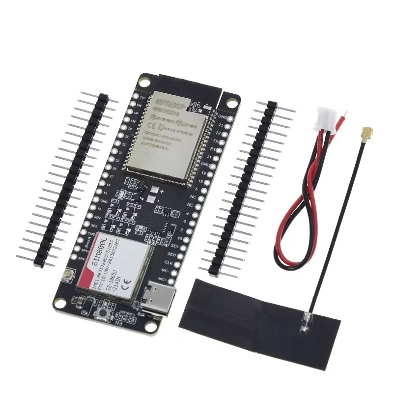
- ESP32 T-Call V1.3 Wireless With GSM SIM800L Module And Antenna
ESP32 T-Call V1.3 Wireless With GSM SIM800L Module And Antenna
the ESP32 T-Call V1.3 Wireless With GSM SIM800L Module And Antenna is a development board based on the ESP32 chipset that includes a GSM/GPRS SIM800L module and an onboard antenna. It is designed for IoT applications that require wireless communication with cellular networks. The board has built-in Wi-Fi and Bluetooth connectivity and supports multiple communication protocols such as MQTT, HTTP, TCP, and UDP. The GSM/GPRS SIM800L module allows the board to communicate with cellular networks using a SIM card.
Package Includes:
- 1 x ESP32 T-Call V1.3 Wireless With GSM SIM800L Module And Antenna
Terms and Conditions
30-day money-back guarantee
Shipping: 2-3 Business Days
Features:
- Based on the ESP32-WROVER-B module with 8MB PSRAM and 4MB flash memory
- GSM/GPRS SIM800L module with quad-band support
- Onboard antenna for wireless communication
- SIM card slot for cellular network connectivity
- Built-in Wi-Fi and Bluetooth connectivity
- Supports MQTT, HTTP, TCP, and UDP communication protocols
- 0.96-inch OLED display for visual feedback
- Includes a CP2104 USB-to-UART converter for easy programming and debugging
- Supports multiple power sources, including USB, battery, and external power supply
- Compatible with the Arduino IDE and MicroPython
- Can be used for a wide range of IoT applications, including remote monitoring, asset tracking, and smart home automation.
Description:
The board is based on the ESP32-WROVER-B module, which has 8MB PSRAM and 4MB flash memory. This provides ample space for storing programs and data, and the PSRAM is particularly useful for applications that require large amounts of memory. In addition to the ESP32 module, the board includes a GSM/GPRS SIM800L module, which allows it to communicate with cellular networks using a SIM card. The module supports a quad-band GSM/GPRS network and has a maximum data rate of 85.6 kbps for both uplink and downlink. The onboard antenna provides reliable wireless connectivity, and the SIM card slot allows you to easily swap out SIM cards as needed. The board has built-in Wi-Fi and Bluetooth connectivity, which can be used to connect to local networks or to other devices. This makes it easy to integrate the board with other IoT devices and services. The board also supports a variety of communication protocols, including MQTT, HTTP, TCP, and UDP. This allows it to communicate with a wide range of IoT devices and services and makes it easy to develop custom applications that meet your specific needs
Principle of Work:
The board can be powered using a USB cable, a battery, or an external power supply. Once powered on, the ESP32-WROVER-B module runs the program stored in its flash memory. You can program the board using the Arduino IDE or MicroPython, which allows you to write custom applications that take advantage of the board's wireless and cellular connectivity. To communicate with a cellular network, you need to insert a SIM card into the SIM card slot on the board. The GSM/GPRS SIM800L module communicates with the cellular network using the SIM card and provides the board with cellular connectivity. The module has an onboard antenna that provides reliable wireless communication, and it supports a quad-band GSM/GPRS network, which makes it compatible with most cellular networks worldwide. The ESP32-WROVER-B module communicates with the GSM/GPRS SIM800L module over a serial interface. This allows the ESP32 module to send and receive data over the cellular network. The board supports multiple communication protocols, including MQTT, HTTP, TCP, and UDP, which makes it easy to communicate with other IoT devices and services. It includes a CP2104 USB-to-UART converter for easy programming and debugging. Additionally, the board is compatible with Arduino IDE and MicroPython, which makes it easy to develop custom applications.
Pinout of the Module:
| Pin Number | Pin Name and Function |
|---|---|
| 1 | 3.3V: Provides 3.3 volts of power to connected devices. |
| 2 | EN: Enables or disables the module. |
| 3-6, 11-12, 15-16, 18-23, 25-28, 30 | GPIO pins for general-purpose input/output. |
| 7 | IO27: GPIO pin. |
| 8 | IO14: GPIO pin. |
| 9 | IO12: GPIO pin. |
| 10 | IO13: GPIO pin. |
| 13 | VIN: Provides power to the board (5-12V). |
| 14 | RX2: Receives serial data. |
| 15 | TX2: Transmits serial data. |
| 17 | IO22: GPIO pin. |
| 19 | SDA: Serial data line for I2C communication. |
| 20 | IO18: GPIO pin. |
| 21 | IO5: GPIO pin. |
| 24 | IO4: GPIO pin. |
| 29 | IO26: GPIO pin. |
| 31 | IO25: GPIO pin. |
| 32-35 | GPIO pins for general-purpose input/output. |
| 36 | GND: Ground connection. |
Applications:
- Internet of Things (IoT) devices
- Remote monitoring and control systems
- GPS tracking systems
- Smart homes and automation
- Wearable devices
- Industrial control systems
- Robotics and automation
- Wireless sensor networks
- Mobile applications and communication devices
Circuit:
No circuit is needed for this example we will control the onboard LED using a phone call and a local webpage.
Library:
To run the code for controlling the on-board LED using a phone call and local webpage, you will need to install the following libraries in Arduino IDE:
- SIM800L library for the GSM module: You can download it from the Arduino Library Manager or from the GitHub repository (https://github.com/vshymanskyy/TinyGSM).
- ESPAsyncWebServer library for the web server: You can download it from the Arduino Library Manager or from the GitHub repository (https://github.com/me-no-dev/ESPAsyncWebServer).
- WiFi library for connecting to the WiFi network: This is a built-in library in Arduino IDE and you do not need to install it separately.
To install a library in Arduino IDE, you can follow these steps:
- Open Arduino IDE and click on the "Sketch" menu.
- Select "Include Library" and then "Manage Libraries".
- In the Library Manager, search for the library you want to install.
- Click on the library name and then click on the "Install" button.
- Wait for the installation process to complete.
After installing the required libraries, you can open the code for controlling the onboard LED and upload it to the ESP32 T-Call V1.3 module.
Technical Details:
- Processor: ESPRESSIF-ESP32 240MHz Xtensa® single-/dual-core 32-bit LX6 microprocessor
- Flash Memory: QSPI flash 4MB / PSRAM 8MB
- SRAM: 520 kB SRAM
- Button: Reset
- USB to TTL: CP2104
- Modular interface: UART、SPI、SDIO、I2C、PWM、TV PWM、I2S、IRGPIO
- On-board clock: 40MHz crystal oscillator
- Working voltage: 2.7V-3.6V
- Working current: About 70mA
- Sleep current: About 1.1mA
- SIM card: Only supports Nano SIM card
- Working temperature range: -40℃ ~ +85℃
- Size & Weight: 78.83mm28.92mm8.06mm (11.77g)
Power Supply Specifications:
- Power Supply: USB 5V/1A
- Charging current: 500mA
- Battery: 3.7V lithium battery
- JST Connector: 2Pin 1.25mm
- USB: Type-C
Wi-Fi:
- Standard: FCC/CE-RED/IC/TELEC/KCC/SRRC/NCC
- Protocol: 802.11 b/g/n(802.11n,speed up to150Mbps)A-MPDU and A-MSDU polymerization,support 0.4μS Protection interval
- Frequency range: 2.4GHz
- Transmit Power: 22dBm
- Communication distance: 300m
Bluetooth:
- Protocol: meet Bluetooth v4.2BR/EDR and BLE standard
- Radiofrequency: with -97dBm sensitivity NZIF receiver Class-1,Class-2&Class-3 emitter AFH
- Audio frequency: CVSD&SBC audio frequency
Software Specification:
- Wi-Fi Mode: Station/SoftAP/SoftAP+Station/P2P
- Security mechanism: WPA/WPA2/WPA2-Enterprise/WPS
- Encryption Type: AES/RSA/ECC/SHA
- Firmware upgrade: UART download/OTA(Through network/host to download and write firmware)
- Software Development: Support cloud server development /SDK for user firmware development
- Networking protocol: IPv4、IPv6、SSL、TCP/UDP/HTTP/FTP/MQTT
- User Configuration: AT + Instruction set, cloud server, android/ios app
- OS: FreeRTOS
Resources:
Comparisons:
The ESP32 T-Call V1.3 module and the standalone SIM800L GSM module can both be used for cellular communication with the GSM network, but there are some differences between them:
- Integration: The ESP32 T-Call V1.3 integrates both the ESP32 microcontroller and the SIM800L GSM module, making it a more compact and convenient option. On the other hand, using a standalone SIM800L module requires an additional microcontroller or development board to control it.
- Pins and GPIOs: The ESP32 T-Call V1.3 has more GPIO pins and interfaces available than the standalone SIM800L module. This makes it more versatile for use in different applications.
- Power consumption: The ESP32 T-Call V1.3 has a lower power consumption than a standalone SIM800L module with an MCU since it has an integrated microcontroller and optimized power management features.
- Software support: The ESP32 T-Call V1.3 has good software support, with libraries and examples available for use with the Arduino IDE and other development environments. The standalone SIM800L module also has software support but may require more effort to set up and integrate with a microcontroller.
- Price: The ESP32 T-Call V1.3 is more expensive than a standalone SIM800L module, but considering the integrated ESP32 microcontroller, the cost may be justified in some applications.
The ESP32 T-Call V1.3 module offers a more integrated and versatile solution for cellular communication with the GSM network while using a standalone SIM800L module with a microcontroller provides a more cost-effective option with more control over the hardware. The choice between the two depends on the specific requirements of the application.