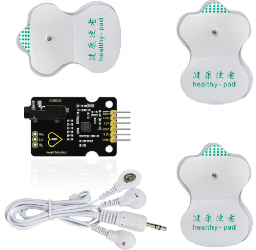
Keyestudio Heart Monitor AD8232 ECG Measurement Module With Sensor Pads
The Keyestudio AD8232 ECG Module is a device for monitoring the electrical activity of the heart. It uses the AD8232 integrated circuit as a front-end for conditioning cardiac bioelectrical signals, making it ideal for heart rate monitoring. The module is low-power and works with a single lead, with included sensor pads for non-invasive measurement.
Package Includes
- 1 x Keyestudio Heart Monitor AD8232 ECG Measurement Module with Sensor Pads
Features
- AD8232 IC for signal conditioning of cardiac bioelectrical signals
- Low power consumption for battery-operated use
- Single-lead ECG monitoring
- Includes sensor pads to attach to the skin
- Versatile for monitoring various vital signs
- Compact size for integration into wearable devices
- Easy to use with clear instructions
- Cost-effective compared to other medical monitoring devices

Specifications
- Power voltage: DC 3.3V
- Output: Analog
- Interface: RA, LA, RL (3-pin, 2.54mm header or earphone jack)
- Dimensions: 36 x 31 x 18mm
- Operating Temperature: -40°C to +85°C

Applications
- Medical Monitoring in hospitals and clinics
- Fitness Monitoring in smartwatches or fitness trackers
- Wearable Devices like smart shirts or patches
- Research studies on heart rate variability
- Home Health Monitoring
- Educational purposes for teaching cardiac physiology
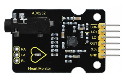
Pin Connections
| Pin Name | Description | Usage |
|---|---|---|
| GND | Power Supply Ground | Ground |
| 3.3V | Power Supply 3.3V | Power Supply |
| OUT (ADC) | Operational Amplifier Output | Connect to ADC input for conditioned heart rate signal |
| LO- | Leads Off Comparator Output (-IN electrode disconnected) | High when -IN disconnected, low when connected |
| LO+ | Leads Off Comparator Output (+IN electrode disconnected) | High when +IN disconnected, low when connected |
| SDN | Shutdown Control Input | Drive low to enter low-power shutdown mode |
| RA | RED Biomedical electrode pad RA (input) | Instrumentation Amplifier Negative Input (Right Arm) |
| LA | YELLOW Biomedical electrode pad LA (input) | Instrumentation Amplifier Positive Input (Left Arm) |
| RL | GREEN Biomedical electrode pad RL (input) | Right Leg Drive Output |
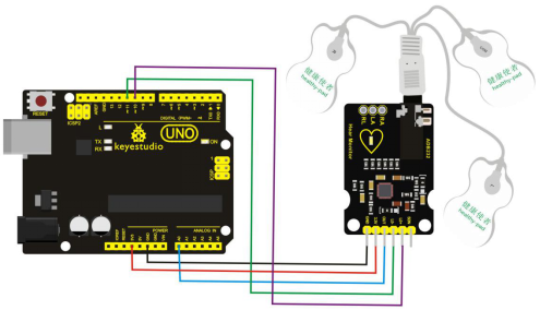
Sample Project
Circuit:
Library
No external library is required.
Arduino Code Example
void setup() {
  Serial.begin(9600);
  pinMode(10, INPUT); // LO+ detection
  pinMode(11, INPUT); // LO- detection
}

void loop() {
  if((digitalRead(10) == 1) || (digitalRead(11) == 1)) {
    Serial.println('!');
  } else {
    Serial.println(analogRead(A0)); // Heart signal
  }
  delay(1);
}
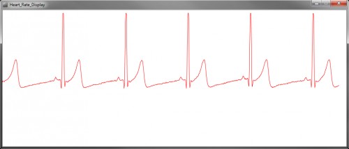
After uploading, you can view the heart rate values on the serial monitor or serial plotter. For advanced visualization, the Processing IDE can be used to plot real-time ECG data.
Notes
- This module is not a replacement for professional medical equipment.
- Consult a qualified healthcare provider for any heart health concerns.
- Follow manufacturer guidelines for accurate and safe usage.
References
- Keyestudio Product Page
- Alibaba Listing
- Keyestudio Wiki
- Components101 AD8232 Module
- ECG Monitoring with AD8232
Features
- AD8232 IC for signal conditioning of cardiac bioelectrical signals
- Low power consumption for battery-operated use
- Single-lead ECG monitoring
- Includes sensor pads to attach to the skin
- Versatile for monitoring various vital signs
- Compact size for integration into wearable devices
- Easy to use with clear instructions
- Cost-effective compared to other medical monitoring devices
Specifications
- Power voltage: DC 3.3V
- Output: Analog
- Interface: RA, LA, RL (3-pin, 2.54mm header or earphone jack)
- Dimensions: 36 x 31 x 18mm
- Operating Temperature: -40°C to +85°C
Applications
- Medical Monitoring in hospitals and clinics
- Fitness Monitoring in smartwatches or fitness trackers
- Wearable Devices like smart shirts or patches
- Research studies on heart rate variability
- Home Health Monitoring
- Educational purposes for teaching cardiac physiology
Pin Connections
| Pin Name | Description | Usage |
|---|---|---|
| GND | Power Supply Ground | Ground |
| 3.3V | Power Supply 3.3V | Power Supply |
| OUT (ADC) | Operational Amplifier Output | Connect to ADC input for conditioned heart rate signal |
| LO- | Leads Off Comparator Output (-IN electrode disconnected) | High when -IN disconnected, low when connected |
| LO+ | Leads Off Comparator Output (+IN electrode disconnected) | High when +IN disconnected, low when connected |
| SDN | Shutdown Control Input | Drive low to enter low-power shutdown mode |
| RA | RED Biomedical electrode pad RA (input) | Instrumentation Amplifier Negative Input (Right Arm) |
| LA | YELLOW Biomedical electrode pad LA (input) | Instrumentation Amplifier Positive Input (Left Arm) |
| RL | GREEN Biomedical electrode pad RL (input) | Right Leg Drive Output |
Sample Project
Circuit:
Library
No external library is required.
Arduino Code Example
void setup() {
  Serial.begin(9600);
  pinMode(10, INPUT); // LO+ detection
  pinMode(11, INPUT); // LO- detection
}

void loop() {
  if((digitalRead(10) == 1) || (digitalRead(11) == 1)) {
    Serial.println('!');
  } else {
    Serial.println(analogRead(A0)); // Heart signal
  }
  delay(1);
}
After uploading, you can view the heart rate values on the serial monitor or serial plotter. For advanced visualization, the Processing IDE can be used to plot real-time ECG data.
Notes
- This module is not a replacement for professional medical equipment.
- Consult a qualified healthcare provider for any heart health concerns.
- Follow manufacturer guidelines for accurate and safe usage.