Features
- Developed jointly by Arduino and Seeed Studio
- Designed for use with Arduino UNO and compatible boards
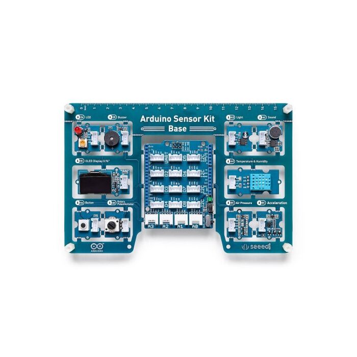
- 10 onboard Grove modules for sensing, input, display, and output
- Pre-connected modules for convenient experimentation
- Includes temperature and humidity, light, sound, air pressure, and 3-axis acceleration sensors
- Integrated 0.96-inch OLED display for displaying readings and messages
- Onboard LED, buzzer, button, and rotary potentiometer for interactive projects
- Grove connectors for connecting additional compatible modules
- Suitable for STEM education, classroom activities, and self-learning
- Supported by Arduino and Seeed Studio learning resources
Principle of Operation
The kit connects its onboard Grove modules to an Arduino-compatible board through a Grove Base Shield. The microcontroller runs an Arduino sketch to read sensor measurements and input states, process the collected data, and control output devices. Sensor readings can be displayed on the OLED screen, while the LED and buzzer provide visual and audible feedback. The rotary potentiometer and button allow users to interact with their programs.
Library
The required libraries depend on the modules used in the project. Install the Arduino board support and relevant libraries through the Arduino IDE Library Manager.
- Arduino IDE: For writing, compiling, and uploading sketches.
- U8g2 or compatible OLED library: For controlling the onboard OLED display, according to the example used.
- Grove Sensor Libraries: Install the appropriate libraries for the onboard temperature and humidity, air pressure, and acceleration sensors when required by the example code.
- Wire Library: For I2C communication with compatible modules.
Refer to the official Arduino Sensor Kit documentation for the recommended libraries, installation instructions, and example sketches.
Code
The following example reads the onboard rotary potentiometer through analog pin A0 and prints the value to the Serial Monitor. Confirm the pin mapping for the board revision before uploading.
void setup() {
  Serial.begin(9600);
}

void loop() {
  int sensorValue = analogRead(A0);

  Serial.print("Potentiometer: ");
  Serial.println(sensorValue);

  delay(200);
}Applications
- Learning Arduino programming and basic electronics
- STEM and classroom electronics education
- Temperature and humidity monitoring
- Light and sound level experiments
- Air pressure measurement demonstrations
- Motion and acceleration detection
- OLED-based sensor data display
- Interactive projects using buttons and rotary controls
- LED and buzzer control experiments
- Rapid prototyping of introductory sensor projects
Pinout

- Digital Grove Headers: 7 connectors associated with D2–D8.
- Analog Grove Headers: 4 connectors associated with A0–A3.
- I2C Grove Headers: 4 connectors for compatible I2C devices.
- UART Grove Header: 1 connector for serial communication.
- OLED Display: Uses the board's designated display interface.
- Rotary Potentiometer: Provides an analog input signal.
- Button: Provides a digital input signal.
- LED and Buzzer: Provide visual and audible output.
- Sensor Modules: Connect through the corresponding onboard Grove interfaces.
Wiring
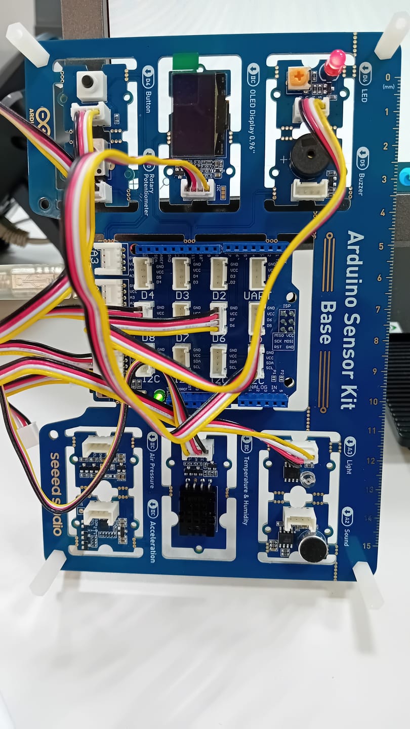
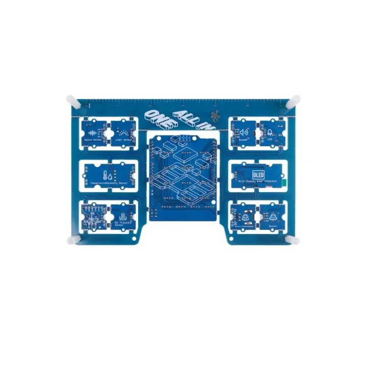
The 10 onboard modules are already connected to the kit PCB, so separate wiring is not required for basic experiments. Connect the Arduino Sensor Kit to a compatible Arduino UNO or other supported board through the Grove Base Shield, then connect the controller to a computer using a suitable USB cable for programming.
- Onboard Modules: Use the pre-connected sensors, controls, display, LED, and buzzer.
- Additional Grove Modules: Connect them to an appropriate Grove header, checking the interface and pin assignment first.
- Programming: Select the correct Arduino board and port in the Arduino IDE before uploading the example sketch.
Important: This kit is not a standalone microcontroller board. An Arduino UNO or compatible controller is required and is not included in the listed package. Check the supported board, operating voltage, and connector pin assignments before attaching additional modules.
Specifications
- Product Type: Arduino Sensor Kit with Grove Base Shield
- Controller Requirement: Arduino UNO or a compatible supported board
- Power Supply: 3.3 V / 5 V, depending on the connected board and module requirements
- Dimensions: 175 x 115 x 28 mm
- Net Weight: 77 g
- Digital Grove Headers: 7, associated with D2–D8
- Analog Grove Headers: 4, associated with A0–A3
- I2C Grove Headers: 4
- UART Grove Headers: 1
- Onboard Modules: LED, buzzer, 0.96-inch OLED display, button, rotary potentiometer, light sensor, sound sensor, temperature and humidity sensor, air pressure sensor, and 3-axis accelerometer
- Programming Environment: Arduino IDE
Resources
Features
- Developed jointly by Arduino and Seeed Studio
- Designed for use with Arduino UNO and compatible boards
- 10 onboard Grove modules for sensing, input, display, and output
- Pre-connected modules for convenient experimentation
- Includes temperature and humidity, light, sound, air pressure, and 3-axis acceleration sensors
- Integrated 0.96-inch OLED display for displaying readings and messages
- Onboard LED, buzzer, button, and rotary potentiometer for interactive projects
- Grove connectors for connecting additional compatible modules
- Suitable for STEM education, classroom activities, and self-learning
- Supported by Arduino and Seeed Studio learning resources
Principle of Operation
The kit connects its onboard Grove modules to an Arduino-compatible board through a Grove Base Shield. The microcontroller runs an Arduino sketch to read sensor measurements and input states, process the collected data, and control output devices. Sensor readings can be displayed on the OLED screen, while the LED and buzzer provide visual and audible feedback. The rotary potentiometer and button allow users to interact with their programs.
Library
The required libraries depend on the modules used in the project. Install the Arduino board support and relevant libraries through the Arduino IDE Library Manager.
- Arduino IDE: For writing, compiling, and uploading sketches.
- U8g2 or compatible OLED library: For controlling the onboard OLED display, according to the example used.
- Grove Sensor Libraries: Install the appropriate libraries for the onboard temperature and humidity, air pressure, and acceleration sensors when required by the example code.
- Wire Library: For I2C communication with compatible modules.
Refer to the official Arduino Sensor Kit documentation for the recommended libraries, installation instructions, and example sketches.
Code
The following example reads the onboard rotary potentiometer through analog pin A0 and prints the value to the Serial Monitor. Confirm the pin mapping for the board revision before uploading.
void setup() {
  Serial.begin(9600);
}

void loop() {
  int sensorValue = analogRead(A0);

  Serial.print("Potentiometer: ");
  Serial.println(sensorValue);

  delay(200);
}
Applications
- Learning Arduino programming and basic electronics
- STEM and classroom electronics education
- Temperature and humidity monitoring
- Light and sound level experiments
- Air pressure measurement demonstrations
- Motion and acceleration detection
- OLED-based sensor data display
- Interactive projects using buttons and rotary controls
- LED and buzzer control experiments
- Rapid prototyping of introductory sensor projects
Pinout
- Digital Grove Headers: 7 connectors associated with D2–D8.
- Analog Grove Headers: 4 connectors associated with A0–A3.
- I2C Grove Headers: 4 connectors for compatible I2C devices.
- UART Grove Header: 1 connector for serial communication.
- OLED Display: Uses the board's designated display interface.
- Rotary Potentiometer: Provides an analog input signal.
- Button: Provides a digital input signal.
- LED and Buzzer: Provide visual and audible output.
- Sensor Modules: Connect through the corresponding onboard Grove interfaces.
Wiring
The 10 onboard modules are already connected to the kit PCB, so separate wiring is not required for basic experiments. Connect the Arduino Sensor Kit to a compatible Arduino UNO or other supported board through the Grove Base Shield, then connect the controller to a computer using a suitable USB cable for programming.
- Onboard Modules: Use the pre-connected sensors, controls, display, LED, and buzzer.
- Additional Grove Modules: Connect them to an appropriate Grove header, checking the interface and pin assignment first.
- Programming: Select the correct Arduino board and port in the Arduino IDE before uploading the example sketch.
Important: This kit is not a standalone microcontroller board. An Arduino UNO or compatible controller is required and is not included in the listed package. Check the supported board, operating voltage, and connector pin assignments before attaching additional modules.
Specifications
- Product Type: Arduino Sensor Kit with Grove Base Shield
- Controller Requirement: Arduino UNO or a compatible supported board
- Power Supply: 3.3 V / 5 V, depending on the connected board and module requirements
- Dimensions: 175 x 115 x 28 mm
- Net Weight: 77 g
- Digital Grove Headers: 7, associated with D2–D8
- Analog Grove Headers: 4, associated with A0–A3
- I2C Grove Headers: 4
- UART Grove Headers: 1
- Onboard Modules: LED, buzzer, 0.96-inch OLED display, button, rotary potentiometer, light sensor, sound sensor, temperature and humidity sensor, air pressure sensor, and 3-axis accelerometer
- Programming Environment: Arduino IDE