Features:
- WiFi Connectivity: Integrated WiFi eliminates the need for external shields or modules.
- Arduino UNO Compatibility: Same form factor and pinout as Arduino UNO for easy integration with shields and sensors.
- Wide Range of I/O Pins: Supports various sensors and peripherals for versatile projects.
- User-Friendly Development Environment: Supported by Arduino IDE with rich libraries and examples.
- Internet of Things (IoT) Capabilities: Easily connect to cloud platforms and remote servers.
- Cross-Platform Compatibility: Works on Windows, Mac, and Linux.
- Open-Source Community and Support: Access tutorials, forums, and community projects.
- Seamless Prototyping: Integrated WiFi and Arduino compatibility enable rapid development.
- Versatile Applications: Ideal for IoT, automation, robotics, and more.
Principle of Work:
- Microcontroller: Based on ATmega4809, handling logic and I/O.
- Programming: Uses Arduino IDE and Arduino language (C/C++).
- Input/Output (I/O) Pins: For sensors, actuators, and more.
- WiFi Connectivity: Integrated module connects to wireless networks.
- WiFi Communication: Enables interaction with servers and cloud services.
- Protocols and Libraries: Supports TCP/IP, HTTP, MQTT, etc.
- IoT Integration: Sends sensor data and receives control commands.
- Power Supply: Powered via USB or external source with onboard voltage regulation.
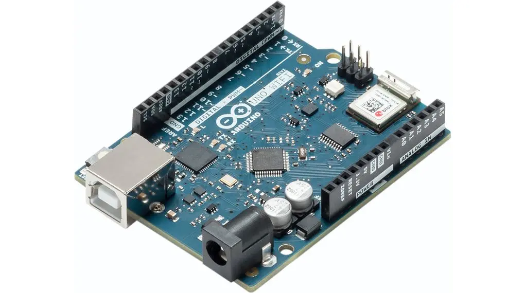
Pinout of the Module:

- Digital Pins: 14 pins (HIGH/LOW logic, 5V/0V).
- Analog Pins: 6 pins (A0–A5) for analog voltage readings (0–5V).
- PWM Pins: 5 PWM-enabled digital pins (~ symbol).
- SPI Pins: MISO and MOSI for SPI communication.
- I2C Pins: SCL (clock) and SDL (data) for I2C communication.
- UART Pins: Rx (receive) and Tx (transmit) for serial communication.
Applications:
- Home Automation
- IoT Projects
- Environmental Monitoring
- Robotics and Automation
- Weather Stations
- Energy Management
- Industrial Automation
- Educational Projects
- Smart Agriculture
- DIY Prototyping
Circuit:
No external circuit is needed. The built-in LED will be used for testing.
Libraries:
No external libraries required for the basic LED test. However, follow these steps to set up the board:
- Install Arduino IDE from official site.
- Connect the board to your PC via USB.
- In Arduino IDE, go to
Tools > Boardand selectArduino UNO WiFi Rev2. - Choose the correct COM port under
Tools > Port. - Upload a test sketch using the Upload button.
- Open Serial Monitor (9600 baud) to view output.
Example Code:
// Pin connected to the LED
const int LED_PIN = 13;

// Time interval for blinking (in milliseconds)
const int BLINK_INTERVAL = 1000;

void setup() {
  // Initialize the LED pin as an output
  pinMode(LED_PIN, OUTPUT);

  // Start the Serial communication
  Serial.begin(9600);
  while (!Serial) {
    // Wait for Serial Monitor to open
  }
  Serial.println("Blinking LED with Serial Monitor Status");
}

void loop() {
  // Turn on the LED
  digitalWrite(LED_PIN, HIGH);
  Serial.println("LED ON");
  delay(BLINK_INTERVAL);

  // Turn off the LED
  digitalWrite(LED_PIN, LOW);
  Serial.println("LED OFF");
  delay(BLINK_INTERVAL);
}
Explanation:
LED_PINis set to pin 13 (built-in LED).BLINK_INTERVALdefines a 1-second delay.setup()initializes the LED and Serial communication.loop()blinks the LED and prints status to Serial Monitor.
Features:
- WiFi Connectivity: Integrated WiFi eliminates the need for external shields or modules.
- Arduino UNO Compatibility: Same form factor and pinout as Arduino UNO for easy integration with shields and sensors.
- Wide Range of I/O Pins: Supports various sensors and peripherals for versatile projects.
- User-Friendly Development Environment: Supported by Arduino IDE with rich libraries and examples.
- Internet of Things (IoT) Capabilities: Easily connect to cloud platforms and remote servers.
- Cross-Platform Compatibility: Works on Windows, Mac, and Linux.
- Open-Source Community and Support: Access tutorials, forums, and community projects.
- Seamless Prototyping: Integrated WiFi and Arduino compatibility enable rapid development.
- Versatile Applications: Ideal for IoT, automation, robotics, and more.
Principle of Work:
- Microcontroller: Based on ATmega4809, handling logic and I/O.
- Programming: Uses Arduino IDE and Arduino language (C/C++).
- Input/Output (I/O) Pins: For sensors, actuators, and more.
- WiFi Connectivity: Integrated module connects to wireless networks.
- WiFi Communication: Enables interaction with servers and cloud services.
- Protocols and Libraries: Supports TCP/IP, HTTP, MQTT, etc.
- IoT Integration: Sends sensor data and receives control commands.
- Power Supply: Powered via USB or external source with onboard voltage regulation.
Pinout of the Module:
- Digital Pins: 14 pins (HIGH/LOW logic, 5V/0V).
- Analog Pins: 6 pins (A0–A5) for analog voltage readings (0–5V).
- PWM Pins: 5 PWM-enabled digital pins (~ symbol).
- SPI Pins: MISO and MOSI for SPI communication.
- I2C Pins: SCL (clock) and SDL (data) for I2C communication.
- UART Pins: Rx (receive) and Tx (transmit) for serial communication.
Applications:
- Home Automation
- IoT Projects
- Environmental Monitoring
- Robotics and Automation
- Weather Stations
- Energy Management
- Industrial Automation
- Educational Projects
- Smart Agriculture
- DIY Prototyping
Circuit:
No external circuit is needed. The built-in LED will be used for testing.
Libraries:
No external libraries required for the basic LED test. However, follow these steps to set up the board:
- Install Arduino IDE from official site.
- Connect the board to your PC via USB.
- In Arduino IDE, go to
Tools > Boardand selectArduino UNO WiFi Rev2. - Choose the correct COM port under
Tools > Port. - Upload a test sketch using the Upload button.
- Open Serial Monitor (9600 baud) to view output.
Example Code:
// Pin connected to the LED
const int LED_PIN = 13;

// Time interval for blinking (in milliseconds)
const int BLINK_INTERVAL = 1000;

void setup() {
  // Initialize the LED pin as an output
  pinMode(LED_PIN, OUTPUT);

  // Start the Serial communication
  Serial.begin(9600);
  while (!Serial) {
    // Wait for Serial Monitor to open
  }
  Serial.println("Blinking LED with Serial Monitor Status");
}

void loop() {
  // Turn on the LED
  digitalWrite(LED_PIN, HIGH);
  Serial.println("LED ON");
  delay(BLINK_INTERVAL);

  // Turn off the LED
  digitalWrite(LED_PIN, LOW);
  Serial.println("LED OFF");
  delay(BLINK_INTERVAL);
}
Explanation:
LED_PINis set to pin 13 (built-in LED).BLINK_INTERVALdefines a 1-second delay.setup()initializes the LED and Serial communication.loop()blinks the LED and prints status to Serial Monitor.